Ubisense Directional Sensors
A Ubisense UWB Sensor is a base station used by the DIMENSION4 Real-time Location System to find the location of objects in real-time. The sensor detects ultra-wideband (UWB) pulses sent by Ubisense tags and then finds the 3D position of the tag.
When compared to other wireless technologies, UWB technology is less affected by multipath interference. UWB Sensors can therefore detect the position of tags more accurately.
You can use UWB Sensors in different types of environments including manufacturing, healthcare, and workplace productivity.
Directional Sensors with 2.5 GHz radio
Some directional sensors are equipped are equipped with a 2.4 GHz radio to receive GPS coordinates from suitable DIMENSION4 tags, such as Multi-mode Tags. See Support for DIMENSION4 tags with GPS receivers for information on configuring sensors to support GPS.
Directional Sensors with High-Gain or External Antennas
For increased coverage, directional sensors can be supplied with high-gain antennas or with the possibility of attaching external antennas. See Features on the Back Panel.
Features on the Front Panel of a Directional Sensor
The features on the front panel of a UWB Sensor, are shown in the following figure.

Front Panel of a UWB Directional Sensor
| Feature | Description |
|---|---|
|
Network Status LEDs |
The three LEDs show the network status and indicate that the sensor is receiving and transmitting network signals.
|
|
Sensor Status LED |
Shows the status of the sensor. |
|
Fiducial Mark |
Indicates the center of the sensor when recording the actual position of the mounted sensor using a Total Station. |
Directional Sensors with High-Gain Antennas
The figure below shows the labels used to identify a directional sensor with a high-gain sensor.

Directional Sensors with External Antennas
The following figure shows the position of the hole to access the SMA Jack for attaching an external antenna.

Features on the Back Panel
The features on the back panel of a UWB Sensor, are shown in the following figure.
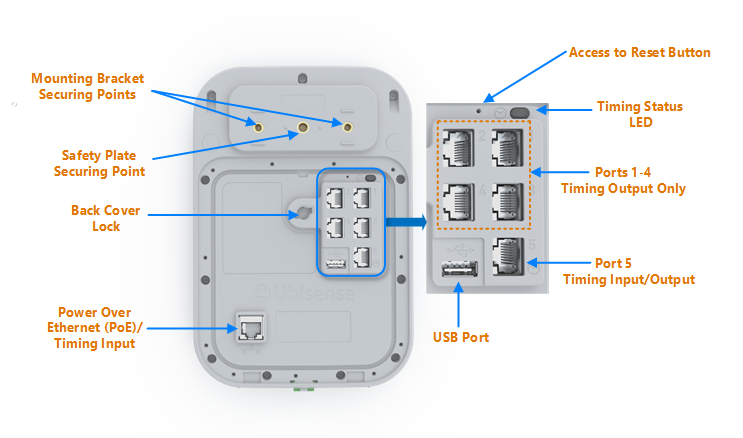
Back Panel of a UWB Sensor
| Feature | Description |
|---|---|
|
Back Cover Lock |
Lock to attach the cover of the back panel. |
|
Bracket Securing Points |
Securing points to attach the sensor to a mounting bracket. |
|
Ports 1-4 |
Ports for distributing timing signals to one or more sensors. |
|
Port 5 |
Port to either receive or distribute timing signals. The clock icon indicates that the port is used for timing input and output. |
|
Power Over Ethernet (PoE) / Timing Input |
The PoE port can be used in the following ways:
For more information about setting up the network and timing cables, see Connecting Network and Timing Cables to Sensors. |
|
Safety Plate Securing Point |
Securing point to attach a safety plate to the sensor. Use the safety plate to fix a safety cable, as described in Attaching a Safety Cable to a Sensor. |
|
Spirit Level |
Indicates the roll of the sensor. For more information, see Setting the Roll of the Sensor to Zero Degrees. |
|
Access to Reset Button |
This hole provides access to the network reset button. For more information, see Returning Sensors to their Default Network Settings . |
|
Timing Status LED |
Indicates the current timing configuration of the sensor. The various statuses are:
The LED does not indicate the timing status. For example, the LED might indicate that the sensor is configured to receive timing signals through a Timing Port. However, the sensor might not be receiving any timing signals. The clock icon indicates that the LED shows the timing configuration of the sensor. |
|
USB Port |
Port intended for future use. |
Sensor Mounting Bracket
The UWB Sensor is shipped with a sensor mounting bracket that you can use for:
- Fixing the sensor to different types of surface such as walls, ceilings, or strut channels.
- Positioning the sensor correctly.
This section describes the features of the mounting bracket, fixing mechanisms for the wall plate and also how to use the Multi-tool.
Sensor Mounting Bracket Features
The features of the sensor mounting bracket are shown in the following figure.
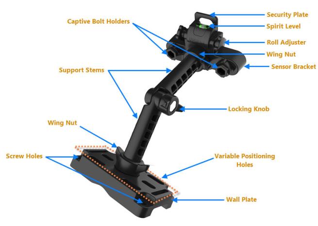
Sensor Mounting Bracket Features
| Feature | Used for... |
|---|---|
| Captive Bolt Holders with M5 Screws | Fixing the bracket to the back panel of the sensor. |
| Locking Knob |
Connecting the support stems and fixing the sensor position at the appropriate angle. |
| Roll Adjuster |
Setting the roll of the sensor to zero degrees (zero roll). Use the roll adjuster in conjunction with the:
For more information, see Setting the Roll of the Sensor to Zero Degrees. |
| Screw Holes | Fixing the wall plate to a surface. |
| Security Plate | Fixing the safety cable to the sensor. |
| Sensor Bracket | Fixing the bracket to the back panel of the sensor. |
| Spirit Level |
Setting the roll of the sensor to zero degrees, which involves confirming that the sensor is not tilted or bent to one side or the other. Use the spirit level in conjunction with the roll adjuster. |
| Support Stems |
Supporting the sensor and positioning it at the correct pitch and yaw. The support stems are attached together with the locking knob. You can move and rotate the support stem to set the appropriate pitch and yaw for the sensor. For more information, see: |
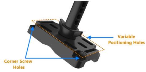
| Variable Positioning Holes |
Fixing the wall plate to a surface by using different types of fixing mechanisms such as U-bolts and pan-head screws. For more information, see Determining How to Fix the Mounting Bracket. |
| Wall Plate |
Fixing the bracket to the required surface, such as a wall or a strut channel. For further information, see: |
| Wing Nuts |
Attaching the support stems firmly to the bracket holding the sensor and the wall plate. The wing nuts have an anti-rotation feature to ensure that the bracket/sensor assembly remains stable, for example if there is vibration or disturbance in the environment where you mount the sensor. |
Alignment and Angle of Support Stems
By default, the support stem connected to the sensor bracket is aligned at an offset of -3 degrees, as shown in the following figure.
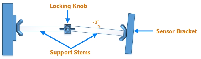
Alignment of Support Stems in Standard Mode
You can move the support stem downwards to set the approximate angles shown in the following figure.
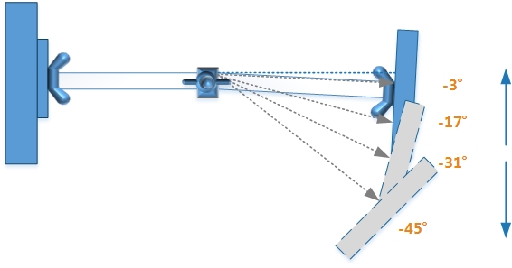
Angles Possible in Standard Mode
These angles have been rounded up for simplicity. For example, in the Standard Mode, the precise angle is -3.5 degrees rather than -3 degrees.
When you completely rotate the support stems so that they are upside down (Rotational mode), they are aligned at an offset of 4 degrees, as shown in the following figure.
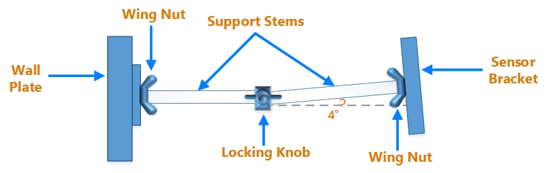
Alignment of Support Stems in Rotational Mode
In Rotational mode, you can move the support stem downwards, to set the following approximate angles:
-
-10 degrees
-
-24 degrees
-
-38 degrees
-
-52 degrees
The position of the sensor changes depending on the angle that you set, as shown in the following figure.
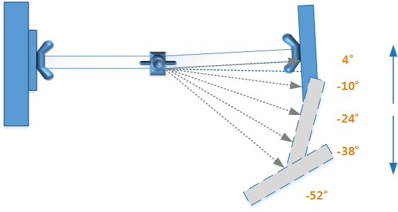
Angles Possible in the Rotational Mode
Wall Plate Dimensions
The wall plate of the mounting bracket is used for fixing the bracket to the required surface, such as a wall or a strut channel. This section provides dimensions of various fixing points on the wall plate.
Corner Holes
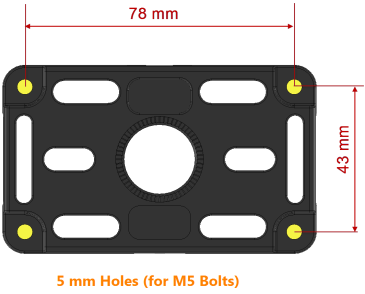
Dimensions of Corner Holes
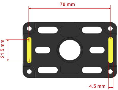
Side Slots
Dimensions of Side Slots
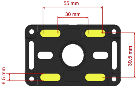
Center Slots
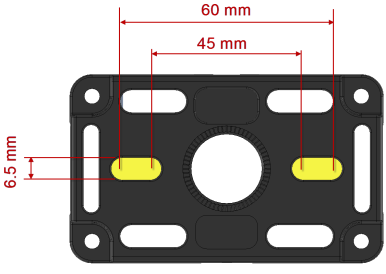
Dimensions of Center Slots
Strap Slots
Dimensions of Strap Slots
Wall Plate Fixing Mechanisms
The fixing mechanism, such as screws or U-bolt, which you use to fix the bracket to the surface depends on the type of surface or object to which the sensor must be fixed. The fixing points on the wall plate are shown in the following figure.
Fixing Points on the Wall Plate
Variable positioning holes include side slots, center slots, and strap slots.
| To Fix the Bracket by Using... | You Require... |
|---|---|
| Screw holes on the corners of the wall plate. |
|
| Screws on the variable positioning slots on the wall plate. |
|
| U-bolt through the variable positioning slots on the wall plate. | Plain washers and Nyloc nuts, or any other lock/nut mechanism. |
The Wiring Contractor is intended to supply fixing materials such as wall plugs or screw anchors (dowels), screws, cable-ties, strut channels, and clamps.
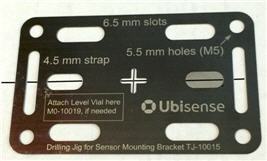
Wall Plate Drilling Template and Jig
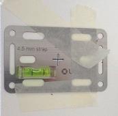
A stainless steel template of the wall plate is available from Ubisense. You can use this to mark the positioning holes, and also when drilling the positioning holes.
When drilling, do not hold the template with your fingers—the edges of the template are sharp and could cause injury if the template rotates suddenly.
To use the template to mark the positioning holes
Align the cross-hairs in the template with the required center position, then mark the holes:
Using the Template to Mark the Position of the Fixing Points
For greater accuracy you can glue a spirit level attachment (available from Ubisense) to the template using a cyanoacrylate. Ensure that the attachment is absolutely level.
To use the template as a drilling jig
Fix the template using a good quality masking tape and then drill the holes:
|
|
|
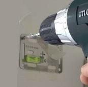
Using the Template as a Drilling Jig
Multi-tool for Securing the Mounting Bracket
A Multi-tool is available for use when securing the mounting bracket and sensor assembly in its final position.
By using the Multi-tool, you reduce the risk of over-tightening the wing nuts on the mounting bracket. Over-tightening the wing nuts may make it difficult to undo them later without damaging the bracket and/or the sensor.
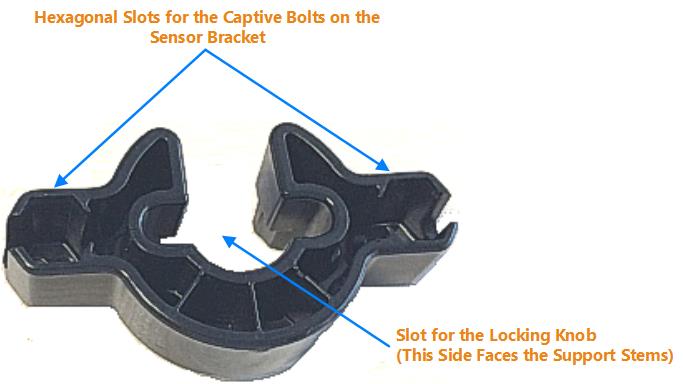
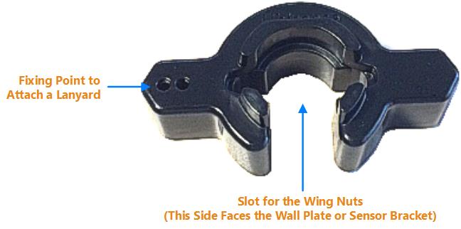
Features of the Multi-tool
Safety Cable
The mounting bracket provides primary support for a sensor. However, if you are mounting a sensor at a considerable height, before attaching the sensor to the mounting bracket, we strongly recommend that you also attach a Sensor Safety Cable to fix the sensor to either a strong surface, or a fixture such as a beam. By using safety cables, you can ensure that the sensors do not fall down if, for example, the Wiring Contractor drops the sensor accidentally when mounting it.
We recommend that you use the Sensor Safety Cable (Part Code: UBIEAZYSFTY) supplied by Ubisense, to protect sensors (see Using Safety Cables to Protect Sensors for further guidance).
The features of the safety cable are shown in the following figure.

Features of the Safety Cable
| Feature | Use for... |
|---|---|
| Clip | Attaching the safety cable to a strong surface or fixture. |
| Loop | Attaching the safety cable to the sensor. |
The cable is supplied with the following components:
- A safety plate.
- A ¼” UNC bolt.
Mounting Sensors
You can mount sensors to different types of surfaces such as walls, ceilings, beams, and cable ducts.
Mounting a sensor involves the following tasks:
- Attaching a Sensor Safety Cable to a sensor to protect it during and after the mounting process.
- Mounting or fixing the sensor by using a mounting bracket.
Roles Involved in Mounting Sensors
The roles and responsibilities of the personnel who are involved in mounting sensors, are listed in the following table.
| Role | Tasks |
|---|---|
| Field Engineers |
|
| Wiring Contractors |
|
If you are managing the mounting process internally, without assistance from Ubisense, ensure that the sensors are mounted by skilled technicians, in accordance with local regulations and restrictions.
Prerequisites
Before you mount a sensor, ensure that:
- You have created a sensor installation plan that identifies the locations where each sensor must be installed.
- You have the required installation material and fixings for mounting the bracket. The fixings that you require for installing the bracket depend on the type of surface to which the bracket must be attached. For more information, see Determining How to Fix the Mounting Bracket.
To identify the sensor during installation, we also recommend that you attach an identification label to the front panel of the sensor.
For a checklist that lists the order in which you must complete the installation tasks, see the Sensor Mounting Checklist.
The Wiring Contractor is intended to supply fixing materials such as wall plugs or screw anchors (dowels), screws, cable-ties, strut channels, and clamps.
Process for Mounting a Sensor
The process for fixing a sensor at the mounting location is shown in the following figure.
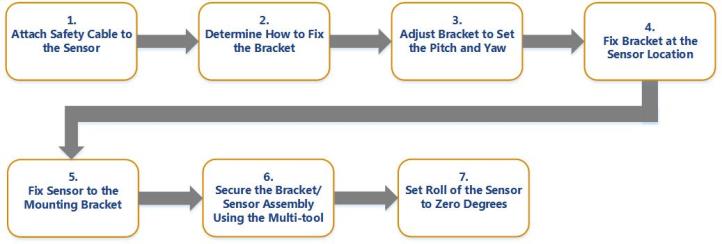
Process for Mounting a Sensor
Before you fix a sensor to a bracket, if you are mounting a sensor at a considerable height, ensure that you have secured the sensor by using a safety cable, as described in Using Safety Cables to Protect Sensors.
Using Safety Cables to Protect Sensors
A safety cable is intended to provide extra security, in addition to the support that the mounting bracket provides to the sensor. The safety cable protects the sensor from falling to the floor, for example, if the sensor or bracket is impacted, or if the sensor is dropped accidentally,
Ensure that you attach a safety cable to a sensor before you fix a bracket to mount the sensor.
Identifying Suitable Locations to Fix Safety Cables
Before you fix a safety cable to secure a sensor, identify suitable fixing points or fixtures to which the cable can be attached. Ensure that the fixing point or fixture is strong enough to hold the sensor and is independent of the bracket mounting. For example, do not attach the safety cable to the base of the bracket.
Attaching a Safety Cable to a Sensor
Before you attach a safety cable to a sensor, ensure that you have the following components, which are supplied with the safety cable:
- Safety plate.
- ¼” UNC bolt. This is the type of bolt that is used with a camera tripod.
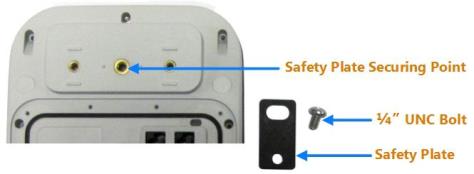
Sensor Securing Point and Safety Plate
To protect a sensor by using a safety cable:
-
Using the ¼” UNC bolt, fix the safety plate to securing point on the back panel of the sensor, as shown in the following figure.
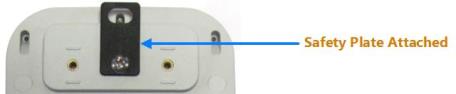
Attaching Safety Plate to the Sensor
-
Insert the loop of the safety cable into the slot on the safety plate, as shown in the following figure.
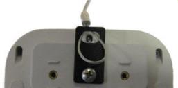
Attaching Safety Cable Loop to the Safety Plate
-
Insert the clip of the cable into its loop, and then pull it tight, as shown in the following figure.
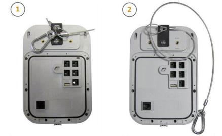
Attaching Safety Cable to the Sensor
-
Pass the clip-end of the safety cable around a fixing point (such as a hook), or a fixture (such as a beam), and then clip it back to the cable.
- Ensure that the fixing point or fixture is independent of the mounting bracket. For example, do not fix the safety cable to the base of the mounting bracket.
- Ensure that the safety cable does not obstruct or cover the front panel of the sensor.
Determining How to Fix the Mounting Bracket
Before you begin, determine how to fix the bracket at the sensor mounting location. You can fix the sensor mounting bracket to a variety of surfaces such as walls, beams, and cable ducts. The following figure shows how you can attach the mounting bracket to a pole clamp and Unistrut® system.
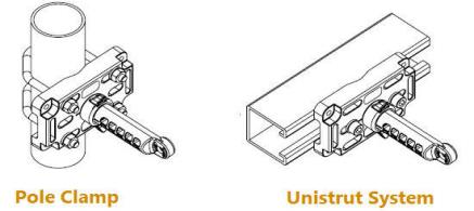
Mounting Bracket Attached to Various Objects
For information about the dimensions of the fixing points on the wall plate and the fixing mechanisms that you can use, see:
Setting the Pitch and Yaw of the Sensor
You can adjust the mounting bracket to set the pitch and yaw of the sensor:
-
Pitch is the vertical angle of the sensor.
-
Yaw is the horizontal angle of the sensor.
The pitch and yaw is shown in the following figure.
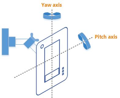
Example of Pitch and Yaw
The pitch and yaw for a sensor vary depending on the location tracking requirements for the installation site.
Examples Showing Pitch and Yaw
Examples of a sensor positioned at a pitch of -41 degrees and -55 degrees, are shown in the following figure.
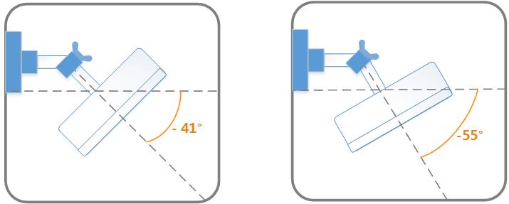
Sensor Positioned at Different Pitch Angles
Examples of a sensor positioned at a yaw of 60 degrees and ‑40 degrees are shown in the following figure. In this figure, the front of the sensor faces North, away from you.
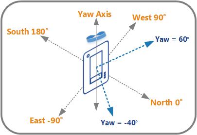
Sensor Positioned at Different Yaw angles
Adjusting the Bracket
There are several adjustment points on the mounting bracket, as shown in the following figure.
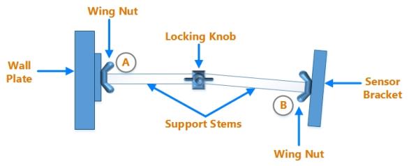
Adjustment points on the Sensor Mounting bracket
Before starting, familiarize yourself with the adjustment points on the mounting bracket:
-
Try rotating the support stem at the wall plate (A). This changes the yaw.
-
Try adjusting the angle of the support stem at the locking knob. This changes the pitch.
-
Try rotating the support stem at the sensor bracket (B). The spirit level on the sensor bracket should be approximately level. You can make fine adjustments to this later.
Setting the position of the sensor is a process of trial and error, and you may need to repeat steps 1 through 3 in order to achieve the correct position.
Fixing the Bracket at the Sensor Location
After you have prepared the bracket and set the required pitch, fix the bracket at the sensor mounting location by using a suitable fixing mechanism such as screws, or a U‑bolt.
The process for fixing the bracket depends on the surface to which you are attaching the bracket, and the fixing mechanism that you use. For more information, see Determining How to Fix the Mounting Bracket.
After you have fixed the bracket, to prevent the bracket from moving, tighten the fixings that connect the wall plate to the surface.
Fixing the Sensor to the Bracket
To fix the sensor to the bracket, you must tighten the two M5 x 25 Hex Head screws, which are supplied with the bracket.
To fix the sensor to the bracket:
-
On the sensor bracket, ensure that the two M5 Hex Head screws are firmly enclosed in their captive bolt holders, with their heads sub-flush; these are interference fits.
-
Place the back panel of the sensor against the sensor bracket. Check that the captive bolt holders are aligned with the securing points on the
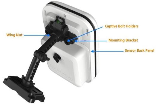
Bracket Aligned with the Securing Points on the Sensor
-
Attach the sensor to the bracket by tightening the captive bolt holders with your fingers.
-
Tighten the wing nut that connects the support stem to the sensor bracket with your fingers.
Securing the Bracket and Sensor Assembly using the Multi-tool
After you have fixed the bracket and mounted the sensor, you must ensure that the bracket and sensor assembly remains strong and resistant to disturbances such as movement and vibration in the surrounding environment.
Tighten all fixings by using the Multi-tool. Do not use any other tools for this purpose.
-
To tighten the wing nuts that connect the support stems to the wall plate and the sensor:
- Using your fingers, check that the wing nuts are reasonably tight. You should be able to undo them without needing any tools.
- Using the Multi-tool as shown below, tighten the wing nuts by an additional two clicks.
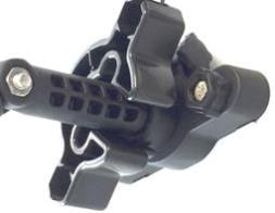
Using the Multi-tool to Secure a Wing Nut
Do not over-tighten the wing nuts as this may make it difficult to undo the wing nuts later without damaging the bracket or sensor assembly.
-
Tighten the locking knob that connects the two support stems of the bracket:
Using the Multi-tool to Secure the Locking Knob
-
Tighten the captive bolts that connect the bracket to the sensor:
Always use the Multi-tool to tighten the captive bolts. Do not use any other tools for this purpose.
-
Place the Multi-tool over the captive bolt and press down on the captive bolt.
-
Tighten with the Multi-tool. When you reach the correct tightness, the tool jaws open and the Multi-tool rotates freely.
Using the Multi-tool to Secure a Captive Bolt
-
Setting the Roll of the Sensor to Zero Degrees
Roll is the amount that the sensor is tilted or bent to one side or the other. Examples of incorrect and correct positioning of the sensor, where the roll is set to zero degrees, are shown in the following figure.
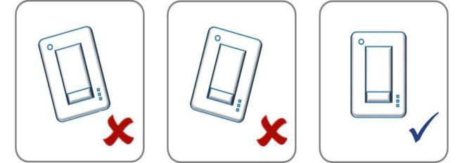
Correct Positioning of Sensor at Zero Roll
Ensure that you set the roll of the sensor to zero degrees by using either the:
-
Spirit level on the sensor mounting bracket.
-
Spirit level under the back panel of the sensor.
Do not check the position of the sensor by visual inspection. You must set the roll to zero degrees by using the spirit level on either the mounting bracket or the sensor.
We recommend that you use the spirit level on the mounting bracket to check the position of the sensor. If you are unable to view this spirit level when mounting the sensor, you can use the spirit level under the back panel of the sensor.
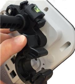
Spirit Level on the Mounting Bracket
The sensor mounting bracket has a spirit level, as shown in the following figure.
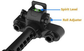
Spirit Level and Roll Adjuster on the Bracket
Spirit Level on the Sensor
Additionally, the UWB sensor has a spirit level under its back panel, as shown in the following figure.
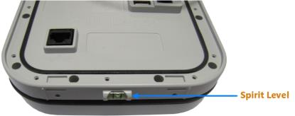
Spirit Level on the Sensor
Reading the Spirit Level Indication
Each spirit level has two markers. The location of the bubble in the spirit level indicates the position of the sensor. The acceptable position of the sensor, as indicated by the bubble in the spirit level, is shown in the following figure.
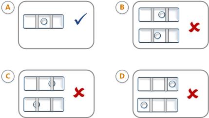
Acceptable Indication on Spirit Level
| Location of the Bubble | Indicates that... | Acceptable (Yes/No) |
|---|---|---|
| A. Centralized between the markers. | The sensor position is at zero degrees. | Yes |
| B. Between the markers. | The sensor position is within 1 degree of being level. | No |
| C. On or below one of the markers. | The sensor position is within 2 degrees of being level. | No |
| D. Outside the markers. | The sensor position is more than 3 degrees of being level. | No |
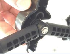
Setting the Roll to Zero Degrees
To set the roll of the sensor to zero degrees:
- Check the location of the bubble in the spirit level.
- Adjust the position of the sensor by using the roll adjuster.
- When the position of the sensor is at zero degrees, retain this position by tightening the wing nut that connects the support stem to the sensor bracket, by using your fingers.
- Recheck the location of the bubble in the spirit level. If there is any backlash, readjust the position of the sensor.
Connecting Network and Timing Cables to Sensors
Before you begin, ensure that you familiarize yourself with the network and timing ports on the back panel of the sensor, as shown in Features on the Back Panel.
To locate the 3D position of a tag, UWB Sensors require the following connections:
- Timing: To record the precise time when the sensor detects a UWB pulse from a tag.
- Network: To receive and transmit information to the DIMENSION4 Real-time Location System.
Depending on your installation requirements, you can either:
-
Supply combined network and timing to the sensors, by using a UbisenseTiming Distribution Unit (TDU). See Ubisense Timing Distribution Unit for information on connecting TDUs.
- Connect separate network and timing cables to the sensors.
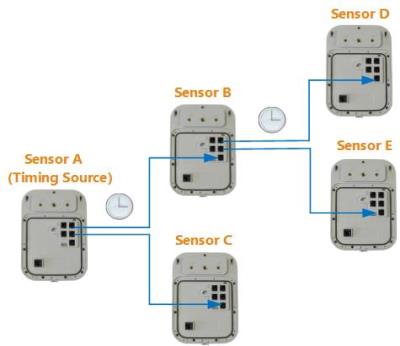
Timing Sources and Timing Trees
You can configure any sensor to work as a timing source. The timing source is at the root of a timing cable tree, and provides synchronization signals to all the downstream or recipient sensors in that tree, as shown in the following figure.
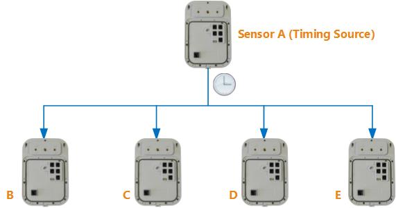
Example of a Timing Tree
When you physically connect two sensors together with a timing cable, the upstream (supplying) sensor controls the timing signal and transmits its MAC address to the downstream (receiving) sensor. The sensors therefore detect the topology of the timing tree automatically.
In a D4 RTLS, multiple timing trees can exist in the same group, as shown in the following figure.
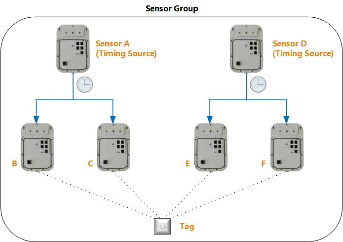
Multiple Timing Trees in the Same Group
Sensors use the Time-difference of Arrival (TDOA) and the Angle of Arrival (AOA) to identify the position of a tag.
The TDOA is only generated between sensors that have synchronized timing. When the D4 RTLS gathers the timing information from two sensors, it first checks if the sensors are synchronized, and then constructs a TDOA. However, all sensors from the group can use the AOA to find the position of the tag.
Guidelines for Setting up Timing
Sensors from a group work together to identify the location of objects and must be connected with timing cables so that they are synchronized.
Sensors from different groups do not share data and therefore do not have to be synchronized.
- Do not connect timing cables between two sensors that are not in the same group.
- Do not set up more than ten hops in a timing cable daisy chain.
- Do not connect timing cables across separate bands of sensors to synchronize disjoint groups.
- Do not create excessive daisy-chaining out of any individual sensor.
Supported Cable Types and Possible Range
UWB Sensors support Unshielded Twisted Pair (UTP) cables for timing and network. Cables must be Cat5e or above. The timing cables are physically the same as unshielded Ethernet cables, and use the same wire and connectors.
Unshielded Twisted Pair Cables are available with either 24AWG or 26AWG conductors. The range that you can cover with these cables, is summarized in the following table.
| Cable Used For... | Possible Range |
|---|---|
|
Timing only |
Either:
|
|
Combined timing and network |
The length is restricted to 100 meters by the Ethernet standard. |
Connecting Separate Network and Timing Cables
Where a TDU is not wanted or required, the sensor, which is not the root timing source, receives:
- Network from a PoE network switch, which is also connected to the Location Platform server.
- Timing from another sensor.
You must therefore connect separate network and timing cables to each sensor.
The root timing source must always be a sensor, which is configured as the timing source.
Connecting Separate Network Cables
If you use separate network cables for sensors, you must connect each sensor by standard 100BASE‑TX Ethernet to a PoE switch, which is also connected to the Location Platform server.
PoE is the only method of supplying power to a sensor. If PoE switches are not available, you can use PoE injectors to supply power to sensors locally from AC mains.
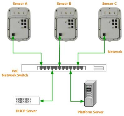
Separate Network Cabling for a Group of Sensors and the Location Platform Server through a PoE Switch
Do not plug a network cable into a timing port, or a timing cable into the network port.
Connecting Separate Timing Cables
If you are not using a TDU, sensors can receive timing either from the timing source or from another sensor that is connected to the timing source. The timing cabling for a group of three sensors is shown in the following figure.

Separate Timing Cabling
Ensure that you connect the timing cables to the correct ports on the sensors. Ports 1 to 4 are for timing output and port 5 is for timing input. For information about network and timing ports, see Features on the Back Panel.
Do not plug a network cable into a timing port, or a timing cable into the network port.
The timing source can supply timing directly to a maximum of five sensors. If you want to supply timing to additional sensors, you can daisy-chain sensors to distribute timing from one or more sensors that are currently receiving timing.
Daisy-chaining Sensors
Daisy-chaining sensors involves distributing timing from a sensor to additional sensors, as shown in the following figure.
Daisy-chaining Sensors
To daisy chain sensors, connect a timing cable from the timing output port on the sensor that is currently receiving timing, to the timing input port on the sensor that requires timing input.
We recommend that you limit the depth of the timing tree to 10 hops or less.
Fixing IP Covers to Sensors
DIMENSION4 sensors come with three levels of ingress protection (IP):
-
IP30: as supplied, a DIMENSION4 sensor has a rating of IP30 making it suitable for general indoor use
-
IP54: fitting the IP54 cover enables the sensor to be used in more challenging indoor environments with protection against dust and water splashes
-
IP69K: fitted with the IP69K cover, a DIMENSION4 sensor can operate in harsh outdoor environments, where protection against dust and high pressure water jets is required, and where extremes of heat and cold may be encountered
This section explains how to fix an IP back cover to the back panel of the sensor. You must fit an IP cover if there are any IP requirements to ensure, for example, that the sensor casing and wiring are not exposed to dust and water.
To achieve the designated IP rating, ensure that you follow instructions completely and correctly.
Fixing the IP54 Cover to the Sensor
This section explains how to fix an IP54 back cover to the back panel of the sensor. The IP54 cover, after fixing to the sensor, is shown in the following figure.
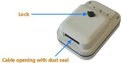
DIMENSION4 Sensor Fitted with the IP54 Cover
To fit the IP54 cover:
- Insert the cables through the opening in the IP54 cover.
- Connect the cables to the sensor.
- Position the cover on the sensor and rotate the lock to fix it.
Depending on the type of cable connector, you may need to arrange the cables to:
- Avoid compressing the cables when the cover is locked.
- Prevent the lock from obstructing the cables.
Fixing the IP69K Cover to the Sensor
This section explains how to fix an IP69K back cover to the back panel of the sensor. A sensor with an IP69K cover is shown in the following figure.

DIMENSION4 Sensor Fitted with the Three-Port IP69K Cover
Ubisense supplies two versions of the IP69K cover:
-
IP69K Cover with one port
Provides an Ethernet connection for installations using combined networking, power and timing signals. See Fixing the Single-Port IP69K Cover to the Sensor for information on fitting a single-port IP69K cover
-
IP69K Cover with three ports
Provides timing in, timing out and Ethernet connections for installations where sensors use separate network and timing cabling. See Fixing the Three-Port IP69K Cover to the Sensor for information on fitting a three-port IP69K cover
Fixing the Single-Port IP69K Cover to the Sensor
Requirements
IP69K Cover Parts
The following shows the IP69K

|

|
| Part | Use for... |
|---|---|
| Network Cable | Plugging into the socket on the back of the sensor. |
| Screws |
11 x Stainless steel screws with Torx T10 head for attaching the IP69K cover to the back of the sensor. |
| TPE Gasket with Location Tab | Correctly positioning the gasket during assembly. |
Equipment
The following additional equipment is required to fit the IP69K cover:
-
Torque screwdriver with up to 1.0 Nm capability and adjustable in 0.1 Nm increments or better, e.g. WERA 7440 (0.3-1.2 Nm)
-
Torx No. T10 bit (min. 30 mm shank recommended)
Mating Connector
See xxxx for information on preparing the HARTING PushPull RJ45 connector (part code 09 45 145 1561 or the previous part code 09 45 145 1560) for use with the IP69K cover.
Preparation
Before attaching the IP69K cover to the sensor, check that:
-
All connectors in the cover and the sockets on the rear of the sensor are clean and free from dust or debris to ensure a good electrical connection
-
The groove in the rear of the sensor is free of dust and debris to ensure that the product becomes water-tight
-
The raised lip around the cover is clean and undamaged
Assembling the Cover and Sensor
To fit the IP69K cover to the sensor:
-
Check (and retighten if necessary) to 0.8 Nm each of the eleven screws on the rear of the sensor in case the screws have relaxed slightly since the original factory assembly.
-
Place the gasket over the slot on the sensor with the location tab at the top of the slot and on the outside (see right), and then gently feed the gasket around and into the slot.
-
Offer the two tabs on the cover to the recesses at the bottom of the sensor; the two parts should loosely hinge together.
-
Plug the network cable on the cover into its socket on the rear of the sensor.
-
Hinge down and hold the cover in place while torquing each of the eleven screws on the perimeter of the cover to 0. 8 Nm.
Preparing the HARTING PushPull RJ45 Mating Connector
xx
Inserting the IP-Rated Network Cable
To insert an IP-rated cable:
-
With the sensor facing downwards, ensure that the eight RJ45 contacts are facing upward and/or the yellow arrows on the connector and cable are aligned.
-
If present, ensure the locking ring is rotated counter-clockwise to allow the connector to slide freely.
-
Firmly push the connector into the housing on the cover until a click is heard.
-
If present, rotate the locking ring clockwise to prevent accidental removal.
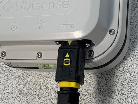
Inserting an IP-rated network cable into the single-port IP69K cover
Fixing the Sensor to the Mounting Bracket
With the IP69K cover fitted, if you cannot fix the sensor to the mounting bracket using the standard securing points (shown in Features on the Back Panel), you can instead use the securing points on the back of the IP69K cover.
Similarly, the safety cable can be attached to a safety plate secured either to the safety plate securing point on the rear of the sensor or on the rear of the IP69K cover itself. See Attaching a Safety Cable to a Sensor for information on attaching a safety cable.
To fix the sensor to the bracket, you must tighten the two M5 x 25 Hex Head screws, which are supplied with the bracket.
To fix the sensor to the bracket:
-
On the sensor bracket, ensure that the two M5 Hex Head screws are firmly enclosed in their captive bolt holders, with their heads sub-flush; these are interference fits.
-
Place the back panel of the sensor against the sensor bracket. Check that the captive bolt holders are aligned with the securing points on the

Bracket Aligned with Securing Points on the IP69K Cover
-
Attach the sensor to the bracket by tightening the captive bolt holders with your fingers.
-
Tighten the wing nut that connects the support stem to the sensor bracket with your fingers.
Fixing the Three-Port IP69K Cover to the Sensor
Requirements
IP69K Cover Parts
The following shows the IP69K

|
|
| Part | Use for... |
|---|---|
| Network Cable | Plugging into the socket on the back of the sensor. |
| Screws |
11 x Stainless steel screws with Torx T10 head for attaching the IP69K cover to the back of the sensor. |
| TPE Gasket with Location Tab | Correctly positioning the gasket during assembly. |
Equipment
The following additional equipment is required to fit the IP69K cover:
-
Torque screwdriver with up to 1.0 Nm capability and adjustable in 0.1 Nm increments or better, e.g. WERA 7440 (0.3-1.2 Nm)
-
Torx No. T10 bit (min. 30 mm shank recommended)
Mating Connector
See xxxx for information on preparing the HARTING PushPull RJ45 connector
Preparation
Before attaching the IP69K cover to the sensor, check that:
-
All connectors in the cover and the sockets on the rear of the sensor are clean and free from dust or debris to ensure a good electrical connection
-
The groove in the rear of the sensor is free of dust and debris to ensure that the product becomes water-tight
-
The raised lip around the cover is clean and undamaged
Assembling the Cover and Sensor
To fit the IP69K cover to the sensor:
-
Check (and retighten if necessary) to 0.8 Nm each of the eleven screws on the rear of the sensor in case the screws have relaxed slightly since the original factory assembly.
-
Place the gasket over the slot on the sensor with the location tab at the top of the slot and on the outside (see right), and then gently feed the gasket around and into the slot.
-
Offer the two tabs on the cover to the recesses at the bottom of the sensor; the two parts should loosely hinge together.
-
Plug the network cable on the cover into its socket on the rear of the sensor.
-
Hinge down and hold the cover in place while torquing each of the eleven screws on the perimeter of the cover to 0. 8 Nm.
Preparing the HARTING PushPull RJ45 Mating Connectors
xx
Removing the Protective Blanking Plugs
The three-port IP69K cover ships with two protective blanking plugs, fitted to the Timing IN and Timing OUT ports. One of both of these plugs will need to be removed, depending on the specific timing cable configuration for the sensor.
To remove a protective blanking plug, pull it firmly outwards.
![]()
Removing a protective blanking plug
Inserting the IP-Rated Network or Timing Cables
To insert an IP-rated cable:
-
With the sensor facing downwards, ensure that the eight RJ45 contacts are facing upward and/or the yellow arrows on the connector and cable are aligned.
-
If present, ensure the locking ring is rotated counter-clockwise to allow the connector to slide freely.
-
Firmly push the connector into the housing on the cover until a click is heard.
-
If present, rotate the locking ring clockwise to prevent accidental removal.
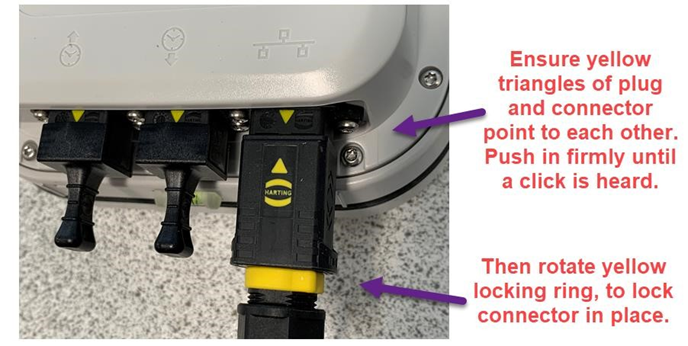
Inserting IP-rated network cables into the three-port IP69K cover
Replacing the Protective Blanking Plugs
After you have connected the cables to the sensor, depending on your timing cable configuration, you may have one or more unused ports. To ensure a water-tight enclosure, you must replace the blanking plugs on any unused ports.
Note: You always require the Ethernet port to be connected even if it is only to provide power to the unit.
To replace a protective blanking plug, push it onto the connector housing until it clicks into place.
Fixing the Sensor to the Mounting Bracket
With the IP69K cover fitted, if you cannot fix the sensor to the mounting bracket using the standard securing points (shown in Features on the Back Panel), you can instead use the securing points on the back of the IP69K cover.
Similarly, the safety cable can be attached to a safety plate secured either to the safety plate securing point on the rear of the sensor or on the rear of the IP69K cover itself. See Attaching a Safety Cable to a Sensor for information on attaching a safety cable.
To fix the sensor to the bracket, you must tighten the two M5 x 25 Hex Head screws, which are supplied with the bracket.
To fix the sensor to the bracket:
-
On the sensor bracket, ensure that the two M5 Hex Head screws are firmly enclosed in their captive bolt holders, with their heads sub-flush; these are interference fits.
-
Place the back panel of the sensor against the sensor bracket. Check that the captive bolt holders are aligned with the securing points on the
Bracket Aligned with Securing Points on the IP69K Cover
-
Attach the sensor to the bracket by tightening the captive bolt holders with your fingers.
-
Tighten the wing nut that connects the support stem to the sensor bracket with your fingers.