Support for DIMENSION4 tags with GPS receivers
Some DIMENSION4 tags contain GPS receivers and can periodically transmit their GPS coordinates via the tag’s onboard 2.4 GHz radio.
From version 3.5 onwards, DIMENSION4 sensors can be configured to receive these transmissions and the DIMENSION4 support services can be configured to transform the GPS latitude/longitude values into tag position events in the user-defined XYZ coordinate system, so that the GPS readings create tag location events that are sent via the Ubisense OTW protocol or the ISO 24730 protocol exactly as though they were generated from UWB transmissions.
The DIMENSION4 support for GPS tags includes features to support:
- Configuring DIMENSION4 sensors to receive GPS signals from tags via the 2.4 GHz radio
- Creating and configuring GPS reference points using the Background objects tab in Location System Config
- Configuring tag type declarations to make best use of the tags’ on-board tremble switches
- Viewing generated XYZ transformations of the tag GPS positions using the Event review tab in Location System Config
- Tracing the tag GPS protocol and XYZ transformation calculation using the Ubisense tracing features
- Configuring advanced parameters in the GPS processing chain
Note: Support for the location of GPS tags by standard Ubisense sensors with radio capability
Sensors Equipped to Provide GPS Support
DIMENSION4 Directional Sensors that are equipped with a 2.4 GHz radio (such as model number D4SENSOR32IP30R) can be configured to receive GPS and the 2.4 GHz Detector Sensor (model number D4DETECTOR32IP30) receives only GPS.
The sensor_health trace messages can be used to identify sensors which have a radio installed and working. If the trace contains the section "|RADIO installed" then the sensor has a working radio; if the sensor has a section "|RADIO absent" then no radio is installed. See
Configuring DIMENSION4 sensors to receive GPS
To configure a DIMENSION4 sensor to receive GPS messages (and forward them to the calculation services), set the sensor’s radio mode to 56, using the Change sensor parameters / Radio / Mode option, or the equivalent Change all parameters / Sensor / Radio / Mode option shown below:
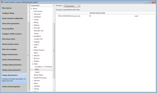
By editing the ‘Sensor / Radio Mode / Value 0’ value on the same screen it is possible to set the receive frequency for the sensor. If the value is left at its default value of zero, the default Ubisense GPS tag frequency (of 2404000 kHz) will be used. Otherwise, the receive frequency in kHz should be used; for example, to use 802.15.4f-2012 channel 15, which is 2401750 kHz, enter 2401750 into the ‘Sensor / Radio Mode / Value 0’ parameter.
Note that, if the sensor supports an external antenna (as in part number D4DETECTOR32IP30), the radio mode does not need to be set in the configuration tool, because the sensor’s internal radio mode will automatically be set to 56 by the sensor’s on-board software. In this case, the value of the radio mode in the configuration tool will have no effect.
Creating and configuring GPS reference points
In order to transform a GPS reading into an XYZ reading it is necessary to define a mapping between the two co-ordinate systems. This is done by creating at least two GPS reference points, which have a position in the XYZ system and also have a latitude, longitude and altitude in the GPS system.
In the ‘Add background objects’ screen of Location System Config, a new ‘reference object’ type ‘GPS reference point’ is now available so that it is possible to drag GPS reference points onto the map.
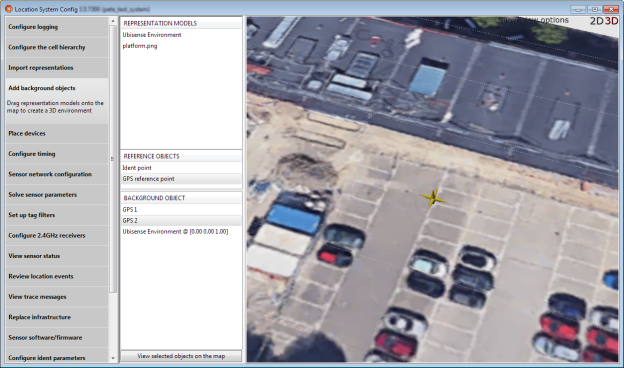
The reference point is shown as a six-pointed gold 3D star. By double-clicking on the reference point, it is possible to configure its name and edit its position.
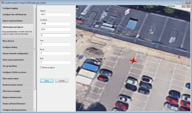
When a reference point has been added, its GPS parameters can be configured in the Change all parameters tab:

Three parameters are required:
- Latitude Degrees North is the decimal number of degrees north of the equator at the GPS reference point.
- Longitude Degrees East is the decimal number of degrees east of the Prime Meridian at the GPS reference point.
- Metres Above Sea Level is the elevation above sea level of the GPS reference point.
The first two parameters should be entered as accurately as possible. The elevation parameter can be significant in an area of high altitude (e.g. more than 1000 m above sea level) but will have little effect on the result for altitudes much below this.
Configuring tag type declarations
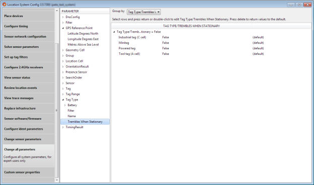
The GPS to XYZ transformation calculation makes use of the tag’s tremble switch as a way of indicating that the tag is moving. But in some cases the tag’s tremble switch will continue to be ‘on’ even when the tag is stationary (for example, if it is attached to a vehicle which will run its engine when stationary, generating enough vibration to activate the tremble switch).
In these cases it is possible to direct the calculation to ignore the tremble switch state by assigning a suitable type to the tag and using the ‘Trembles When Stationary’ attribute of the type to assert that the tag will still tremble even when stationary. This is set by setting the Change all parameters / Tag Type / Trembles When Stationary parameter:
Viewing generated XYZ positions of the tag
When a tag GPS reading is received by a sensor, it is forwarded to the ‘Ubisense / Location system / Location sink’ service in the location cell that owns the sensor. The service will then process the tag’s GPS data, using the GPS reference points that were defined, to transform it into a XYZ data. This XYZ data is then logged to the logging services (if they are running) so that it can be viewed in the Review location events tab in Location System Config.
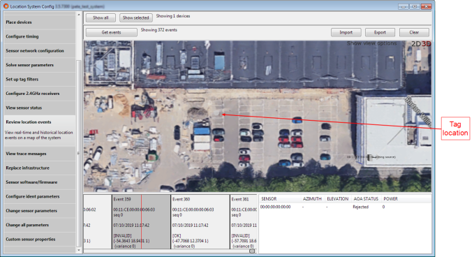
The position of the tag is displayed in gray (here it is in the leftmost column of parking spaces, about 8 m above the two cars).
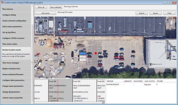
This ‘raw’ XYZ data is then processed by a median filter in the service. Normally this will result in the generation of another location event, which is a valid tag XYZ reading to be sent out. This event is transmitted to clients using the Ubisense OTW protocol or the ISO 24730 protocol, and another event is also logged for viewing in the event review tab, in this case with the tag’s location shown in red, indicating that this is a valid location:
Tracing the tag GPS protocol and calculation
The ls_sink_gps trace stream
The trace stream ‘ls_sink_gps’ will print a trace of processing events from the location sink’s GPS processing. This is not intended to be enabled during GPS operation, but can be a useful aid to understanding the transformation from GPS to XYZ and debugging misconfigurations.
The trace stream messages cover the following events, which occur in sequence in the processing pipeline.
Message reception from the sensor
When the location sink service receives a message from the sensor it prints out its contents
Rejection of duplicate packets
Each sensor listens on two antennas, and multiple sensors may be listening for GPS packets, therefore a packet from an individual tag may result in several GPS packets being received at the location sink. The tag transmits a sequence number in each packet, and to ensure correct processing the location sink will record the sequence number of the last accepted GPS reading and then reject any subsequent packets that have the same sequence number for the given tag. When this happens it will print the message:
Flushing filter state when the tag is moving
If the tag tremble switch is on and either the type of the tag is not set, or the type of the tag is set to a type that is asserted to not tremble when stationary (the default state for a tag type), then the processing will deduce that the tag is moving. The processing maintains some outlier rejection state that assumes that the tag is stationary, so when the tag is moving the state is not valid and must be deleted.
When this happens the location sink will print the message:
Setting up the GPS-XYZ mapping using the reference points
Before processing its first tag event, and every 60 seconds thereafter, the location sink will update its GPS reference points. Two reference points are required in order to create a GPS-XYZ mapping, and if the service cannot find two reference points it will print this message:
If two reference points are retrieved then the service will print out the points that it did get, together with the derived data that is used for building the mapping, as follows: the earth’s radius (the mapping approximates to the Earth’s oblate spheroid geometry by considering it as a sphere whose radius is determined by the latitude and altitude); the distance between the reference points calculated in the XYZ system and in the lat/long system (these values should be close together, and this is a useful check on the configuration); the bearings from one point to another in the XYZ system and in the lat/long system and thus the rotation between the two co-ordinate systems. The sequence of messages looks like this:
ls_sink_gps: earth radius at latitude <mean latitude> = <radius of earth, calculated from mean latitude and altitude>
ls_sink_gps: p1-p2 distance:<distance> (lat/long):<distance> (xy grid)
ls_sink_gps: p1-p2 bearing in XY system = <angle> degrees ls_sink_gps: p1-p2 bearing in LL system = <angle> degrees
ls_sink_gps: rotation LL -> XY = <angle> degrees
Note that the mapping algorithm assumes that the latitude/longitude angle between the two reference points is small, so that the GPS coordinate system near the reference points can be approximated by a Cartesian system in which there is an XY plane which touches the earth’s surface. If this is not possible then it is possible to define multiple mappings, with a different mapping for each Geometry cell. To do this, just place two reference points in each of the Geometry cells that require their own separate mapping – the location sink service will always prefer points that are physically inside its parent Geometry cell.
Rejecting the calculated XYZ if it is too far from the sensor
If the calculated position in the XYZ system is found to be so far from the receiving sensor that it would have been beyond the reception range of the sensor, then the reading is rejected as failing a sanity check. When this happens this message is printed:
Filtering the reading using a median buffer
If the XYZ position has not been rejected by this stage, it is accepted as suitable for insertion into the filtering buffer, and this message is printed:
This value is the same as the raw reading logged in the event review screen.
Extracting a median value for assertion
The outlier rejection filter uses a buffer of readings from which it selects the median value for assertion. The length of the buffer can be specified using the advanced parameters below.
When a suitable median value is selected then a location event is pushed into the clients (via the OTW or ISO 24730 protocols) and the asserted reading is logged in the event review screen, and this message is printed:
ls_sink_gps: injecting <tag id> at <position>
Enabling Clipping Regions with GPS Tag Positions
From version 3.6, a global configuration parameter ls_gps_enable_clipping enables clipping of GPS tag positions.
When this parameter is set, if a sensor forwards a GPS packet from a GPS tag, and that sensor is in one or more groups, then the forwarded packet will only result in a location event for the GPS tag if its derived position lies within the clipping region of one of the groups.
Configuring advanced parameters
There are some advanced parameters available to the location sink. These should not normally require changing but they may be changed by advanced users who have a clear understanding of the implications of their actions.
|
Parameter |
Default value |
Purpose |
|---|---|---|
|
ls_gps_gdop |
10.0 |
Not currently used. Do not modify. |
|
ls_gps_gdop_min |
0 |
The minimum acceptable value of GDOP. For RTK-GPS deployments, GDOP values are: 2=no correction, 3=differential correction, 4=partial RTK fix, 5=locked RTK fix. |
|
ls_gps_gdop_max |
very large |
The maximum acceptable value of GDOP. For RTK-GPS deployments, GDOP values are: 2=no correction, 3=differential correction, 4=partial RTK fix, 5=locked RTK fix. |
|
ls_gps_stderr |
10.0 |
The value to be used as the error estimate in meters when sending location events using the OTW protocol. |
|
ls_gps_range |
300.0 |
The expected maximum range in meters at which a sensor can pick up a GPS tag transmission. |
|
ls_gps_buf_min |
3 |
The minimum length of the median buffer (defaults to 3, must be >1, and will be increased to the nearest odd number). |
|
ls_gps_buf_max |
11 |
The maximum length of the median buffer (defaults to 11, must be < 101, and will be increased to the nearest odd number). |