Solving Sensor Parameters
After you have booted the sensors successfully, you can calculate the orientation and timing for the sensors by running the Solver. During this process, the Solver calculates:
-
The yaw and pitch for each sensor, to determine the correct angle at which the sensors receive signals from a tag.
-
The cable delay or the time required for the timing signal to reach each sensor. This delay must be calculated to determine the TDOA.
The D4 RTLS uses these values to identify the location of tags.
- Before running the Solver, we recommend reviewing events on the Review location events tab in order to check that events are occurring.
- You can copy a tag ID from the timeline (by selecting and pressing Ctrl+C) and paste it into the Solve sensor parameters tab.
To run the Solver:
-
Place a tag in a known position.
You can enter the tag’s location into the Solver either by inputting the tag’s coordinates or by choosing a survey point at which the tag is located.
-
Run the Solver to calculate the yaw, pitch, and cable delay values for the sensors that can see the tag and which are in the same timing tree.
You can run the Solver multiple times for the same sensors. Each solver run captures statistics from hundreds of readings. The D4 RTLS uses the best results based on the lowest standard deviation.
The Solver results of individual sensors affect the group summary. Therefore, you must also run the Solver after you have:
-
Physically moved a sensor and recorded the move on the Replace infrastructure tab.
-
Replaced a timing cable and recorded the swap on the Replace infrastructure tab.
Running the Solver for the Correct Sensors
The Solver calculates the sensor orientation and cable delay values based on the specific position of a reference tag.
When you run the Solver, it lists all the sensors that can detect signals from a reference tag. If one or more sensors only have a partial line of sight to the tag (see the following example), the Solver might return inaccurate results for those sensors. Therefore, ensure that you run the Solver only for those sensors that can directly sight the tag.
An example sensor group that contains sensors with different orientations, is shown below.
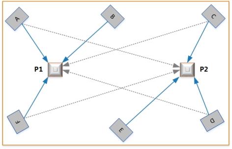
Choosing Sensors when Running Solver
In this example, the sensor parameters are solved with the tag at two different positions, P1 and P2. The sensors can sight the tag as summarized in the following table.
| Tag Position | Direct Line of Sight | Partial Line of Sight |
|---|---|---|
| P1 | Sensor A, Sensor B, and Sensor F | Sensor C and Sensor D |
| P2 | Sensor C, Sensor D, and Sensor E | Sensor A and Sensor F |
If you solve parameters with the tag at P1, the Solver lists Sensors C and D, even though they can only sight the tags partially. If you include these sensors in the Solver run, the orientation results for these two sensors will be inaccurate.
To obtain accurate results for Sensors C and D:
-
Exclude these sensors from the Solver run when the tag is at P1.
-
Solve parameters for these sensors when the tag is at P2.
Prerequisites
Before running the Solver, ensure that you have:
- Configured logging, as described in Configuring Logging. This enables the Solver to obtain data from sensors.
- Added sensors to groups and positioned them, as described in Positioning Sensors. This enables the Solver to calculate orientations and cable delays.
- Configured timing and set the appropriate sensors as timing sources, as described in Configuring Timing Sources.
Running the Solver
You can run the Solver multiple times for the same sensors. The D4 RTLS uses the best results based on the properties of the received signals.
Before you begin:
-
Place a tag in a position at which the sensors can sight it.
-
Ensure that you have the tag ID and the position of the tag in meters.
You can also indicate the tag’s position by placing it a survey point. See
To calculate accurate orientation and timing values for each sensor that can see the tag:
- Run the Solver.
- Review, accept, and save the required results.
- Check that the tag is being accurately located, and then close the solver run.
Start a Solver Run
To start a Solver run:
-
On the Solve sensor parameters tab, click Solve.
Notes:
- If you have not yet run the Solver or if a sensor from a group does not have any result (for example, it cannot detect the tag), then the group summary appears as Incomplete.
-
To view the Solver status of individual sensors from the group, expand the group. Sensors that do not have any results show:
-
The estimated pitch and yaw, if you have provided these values.
-
A timing result of Not done.
-
-
Either:
-
Type the complete tag ID and the X, Y, Z coordinates (in meters) of the tag that you have placed, and then click Start.
or
-
Select Use survey point, choose a survey point from the dropdown, and then click Start.
The survey point’s X, Y, Z coordinates are filled automatically.
Notes:
-
It can take some time for all sensors to appear on the screen.
-
Results are only displayed when you select the checkboxes for one or more of the sensors listed in the Store results area.
-
The Solver captures statistics from hundreds of readings for the selected sensors. The values displayed on the screen are continuously updated based on new readings. The values stabilize when the readings are consistent.
-
- The next step is to review and accept the results.
Review and Accept Results
After running the Solver, the Solve sensor parameters tab shows results for the selected sensors, in a three-column layout, as shown in the following example:
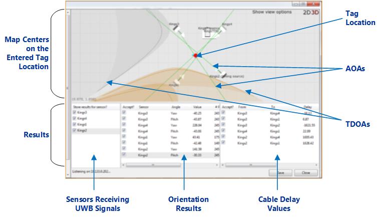
Solver Window
To review and accept results:
-
In the first column, the Solver lists all the sensors that can detect UWB signals from the tag. Select only those sensors that have a direct line of sight to the tag (see Running the Solver for the Correct Sensors).
-
In the second column, the Solver lists the calculated pitch and yaw for each sensor. Select the results that you want to use.
Notes:
- Even if the standard deviation is low, accept the results only if they correspond to the physical orientation of the sensors.
-
If the results of a sensor are consistently poor:
- Solve parameters for the sensor by placing a tag in a different measured position.
- Check and adjust the physical orientation of the sensor, if necessary.
- Check if there are any obstructions that might affect the ability of the sensor to sight the tag.
-
In the third column, the Solver lists the cable delay between sensor pairs—by default all checkboxes in this column are selected for you.
Notes:
- The results for a sensor pair do not appear if a timing signal path from the sensors to the timing source does not exist.
-
If the results are not generated or are consistently poor:
- Check that you have set up correct timing sources and cabling options for sensors.
- Check that the physical cables have been connected to the correct ports on the sensors, as described in
-
When the readings are stable, save the results.
The results displayed on the screen are updated even after you save your solver run. If you click Save again, the new results replace the existing values in your solver run.
- The next step is to check the results of the operation.
Check the Operation
After saving the solver run, check its outcome.
The following screenshot shows an example of sensors with OK results.
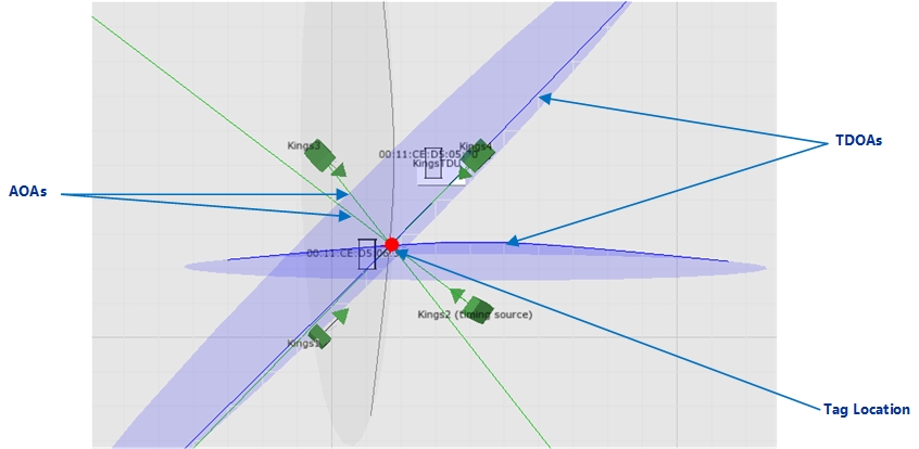
Sensors with OK Orientation Results
Orientation Results
The color of the sensor shows the orientation results for that sensor:
- Green: the orientation results are acceptable (OK).
- Yellow: the orientation results are poor.
- Grey: there are no orientation results.
The TDOAs and AOAs show that the filter is using the results when:
-
The color of the TDOAs changes to blue. The TDOAs also intersect at the tag location.
-
The color of the AOAs is green.
For information on setting up filters, see Setting up Tag Filters.
Timing Results
To check the timing results, close the solver run, and review the information shown in the summary table.
Reviewing Solver Status
The Solver records the sensor orientation and timing (cable delay values) for the group as a whole and also individual sensors from the group. The result of an individual sensor affects the overall result of its group. For example, if a sensor does not have a result, the summary of the entire group appears as Incomplete.
Sensor Results
The possible Solver results for sensors are summarized in the following table.
| Sensor Summary | Description |
|---|---|
| OK | The results are acceptable, as they have a low standard deviation. |
|
OK (Partition N) |
This indicates that timing has been solved for separate sets of sensors within a group (i.e. the partitions) but that there is not enough information to calculate timing between these sets. This will lead to inability to compute TDOA for sightings involving sensors from the different sets. Resolving this requires running the solver for a tag located in sight of some sensors from both sets. |
| Not done | The sensor does not have any Solver results yet. |
| Poor |
The results have a high standard deviation and therefore may or may not acceptable. For information on resolving poor results, see Review and Accept Results. |
Sensor Group Summary
The possible statuses for sensor groups are summarized in the following table.
| Group summary | Description |
|---|---|
|
OK |
All sensors from the group have acceptable results. |
|
Incomplete |
A sensor group has this status when:
|
|
Poor |
The results for one or more sensors from the group are poor. For information on resolving poor results, see Review and Accept Results. |
Viewing and Modifying Solver Runs
You can modify existing Solver runs to accept or reject individual values that were calculated for a particular sensor.
To view and modify a solver run:
-
On the Solve sensor parameters tab, select the required sensor group or sensor. All solver runs that apply to the selected sensor group or sensor are listed.
-
To view or modify a solver run, double-click the required solver run.
The solver run lists the yaw, pitch, and cable delay values for all sensors that were included in that run.
-
Accept or reject the values as required.
To reject a result, clear the Accept? checkbox.
-
Close the solver run.
The status of the sensor and its group are updated.
Notes
-
The overall pitch, yaw, and cable delay values of a sensor are calculated from multiple solver runs. When you modify a solver run, the overall values are recalculated.
-
If sufficient readings or solver runs are not available for determining the pitch, yaw, and cable delay values of a sensor:
-
The sensor shows the estimated yaw and pitch and/or a timing result of Not done.
-
The orientation and/or timing status of the sensor group changes to Incomplete.
-