Importing Representations and Adding Background Objects
A representation is a 2D representation or 3D model, such as a map, floor plan, or objects in the physical location tracking environment. For example, you can use a map as a guide when placing sensors and TDUs.
Representations, such as a map, are optional. They are intended to help you with placing sensors. They do not affect the functionality of your D4 RTLS. However, if you want to use representations, you must size and scale them accurately.
Setting up a map and other background objects involves:
-
Importing a background representation and any other additional models that represent various objects from your physical environment.
-
Scaling (resizing) and modifying the alignment and position of each representation, as necessary.
-
Placing these objects as required.
To accurately resize, scale and rotate the map representation of the site, you need to know the X, Y coordinates of two locations at the site. For best results, these locations should have been accurately measured using a Total Station.
Supported File Types
You can import the following file types:
-
Bitmap (.bmp)
-
COLLADA (.dae)
-
Graphics Interchange Format (.gif)
-
JPEG (.jpg and .jpeg)
-
OpenSceneGraph (.osg)
-
Portable Network Graphics (.png)
-
Scalable Vector Graphics (.svg)
Importing Representations
Importing representations is optional. If required, you can import representations to:
-
Provide a background, such as a floor plan, on which you can place other objects and sensors.
-
Represent objects and items, which you can use as a guide when placing sensors.
To import a background representation and any other additional objects:
-
On the Import representations tab, import the images of the required background representations and objects.
-
Resize and reposition each representation as required, by modifying the following settings.
To enter a value, click to select the row and then click again to make the box editable.
For 3D images, switch between the different axes using the TOP VIEW, FRONT VIEW, and SIDE VIEW options.
Setting Enables you to... Size and Scale
Resize the representation to the required measurements and scale. You can resize representations, including map representations, by using the Reference Points tool. See Transforming a Map Representation by Using Reference Points.
Origin
Move the origin to the required position in the representation. For information on the importance of the origin for the background image, see Defining the Origin.
Rotation
Adjust the orientation (in degrees) of the representation using the following options.
Yaw: The horizontal angle of the image.
Pitch: The vertical angle of the image.
Roll: The amount that the image is tilted to one side or the other.
-
If you need to reset the representation to its initial values, click Reset transformation.
The settings are saved.
Rotating a Representation
To rotate an image, click and then drag the arrows clockwise or anticlockwise:
Additional Features for Positioning Representations
To position images correctly, you can also use the view options that are listed in the following table.
| Feature | Enables you to... |
|---|---|
|
Show axis lines |
View the X, Y and Z axes, so that you can position the image at the required coordinates. |
|
Show scale |
View the actual height and width of the image. |
|
Show bounding boxes |
View the boundaries or the full extent of the image. |
|
Show reference points |
For details, see Transforming a Map Representation by Using Reference Points. |
Exporting Representations
To copy the image to a local directory, click the Export button.
Transforming a Map Representation by Using Reference Points
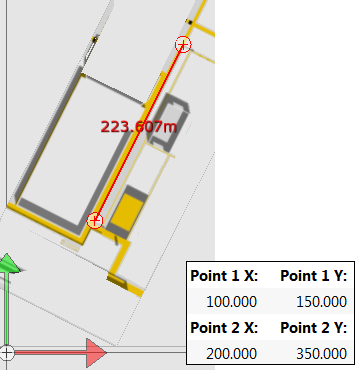
You can resize, scale, rotate and set the origin of the map representation in one step if you know the X, Y coordinates of two locations at the site. This will produce the most accurate results if the locations are as far apart as possible.
Transforming a Representation Based on the X, Y Coordinates of Two Known Locations
You resize, scale and rotate the map representation using the Reference Points tool:
To transform a map representation based on known coordinates:
- On the Import representations tab, select the map representation.
- In the workspace, click the TOP VIEW option.
- Click to turn on Show reference points.
- Position the two ends of the reference line on the two locations.
- Enter the X, Y coordinates of the first location in the Point 1 X, Point 1 Y fields.
- Enter the X, Y coordinates of the second location in the Point 2 X, Point 2 Y fields.
The representation is then transformed. The transformation sets the correct values for:
- size, as shown in the Size X, Y fields
- offset from the origin, as shown in the Origin X, Y fields
- scale factor, as shown in the Scaling X, Y fields
- rotation, as shown in the Yaw field
Defining the Origin
Before you place images, ensure that you define the origin for:
- Background representations: The origin marks the 0,0,0 coordinates that identifies the point, relative to which the sensor positions were measured. Transforming a Map Representation by Using Reference Points describes how to resize, scale, rotate and set the origin of the background representation in one step.
- Other images: You can use the origin to mark the central point of an object, which can make it easier for you to place objects by using absolute coordinates.
To mark the origin of an image:
-
On the Import representations tab, select the required image.
-
Click and drag the origin to the required position in the image, as shown in the following figure:
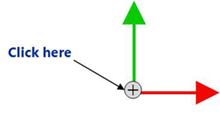
The updated X,Y,Z coordinates are displayed on the left.
-
Adjust the origin using the Origin X, Origin Y and Origin Z fields.
Placing Background Representations and Objects
After you have imported and adjusted the required images, you can place these objects as required
In addition to images you have imported, listed on the left-hand side of the Add background objects tab are Ubisense-supplied representations for:
-
GPS reference points, described in Creating and configuring GPS reference points
-
Ident points, described in Adding and Positioning Ident Points
-
Survey points, which can be used when solving sensor parameters, described in Solving Sensor Parameters
These Ubisense-supplied representations can be placed in the same way as any other representations. Survey points can also be imported using the ubisense_ls_survey_admin tool.
To place objects:
-
Click the Add background objects tab. All the background representations and images that you have imported are listed at the top.
-
Select and drag the background representation to the screen. The background object is listed at the bottom—double-click the object to display an editor in which you can adjust the location and orientation of the background representation.
-
Select and drag additional objects to the screen.
-
Following the onscreen instructions, place and position the additional objects on the background representation, as required.
Importing Survey Points
There are two methods for adding survey points:
-
Like other background objects, in the Add background objects tab, you can drag Survey point reference objects onto the map
-
You can use the ubisense_ls_survey_admin command-line tool to import named survey points and their positions
Downloading the ubisense_ls_survey_admin tool
To get the ubisense_ls_survey_admin tool, run Application Manager, open the DOWNLOADABLES task, and expand Location system /Administration tools. Select ubisense_ls_survey_admin and click Download selected items. Optionally, change the download destination directory. Click Start download.
Using the ubisense_ls_survey_admin tool
The tool can import named survey points individually from the command-line or from a file of survey points. In either case, each point must be specified on its own line in the format "NAME","X","Y","Z".
For example, take a file survey-locations.csv with the following survey points:
"SP1","1","12","0.5"
"SP2","10","12","0.5"
"SP3","15","12","0.5"
"SP4","21","11","0.5"
Running the tool in import mode sets the specified positions.
C:\>ubisense_ls_survey_admin import < C:\Ubisense\survey-locations.csv
creating SP1 at [1,12,0.5]
creating SP2 at [10,12,0.5]
creating SP3 at [15,12,0.5]
creating SP4 at [21,11,0.5]
set 4 survey point positions
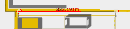
You can see the positioned survey points by opening the Add background objects tab in LSC:

If you want to replace all current survey points with new ones, run the tool with the replace-all option:
ubisense_ls_survey_admin import < new-locations.csv --replace-all
You can also collect the positions of survey points currently in DIMENSION4 by running the tool in export mode.
Deleting an Object
To delete an object, and its representation:
-
Click the Add background objects tab. The BACKGROUND OBJECT section lists all the representations that you have added and placed.
-
Select the object that you want to delete, press the Delete key, and click Delete to confirm the deletion.
You can also double-click the object on the map and, in the editor, select Remove object and click Save.
The object is removed. However, the representation is still retained in the D4 RTLS.
-
To delete the representation:
- On the Import representations tab, locate and select the image that you want to delete.
-
Press the Delete key and click Delete to confirm.
The representation is removed from your D4 RTLS.