Configuring Timing
Sensors use timing signals to record the precise time at which they detect a UWB pulse from a tag and then generate TDOAs that are used for identifying the tag location.
Configuring timing involves:
-
Setting up one or more sensors as timing sources.
-
Defining how other sensors receive timing signals.
Timing Sources and Timing Trees
The timing signal is always generated by a sensor that has been designated as a timing source. The timing source is at the root of a timing cable tree, and provides synchronization signals to all the downstream or recipient sensors in that tree.
When two sensors are connected with a timing cable, the upstream (supplying) sensor controls the timing signal and transmits its MAC address to the downstream (receiving) sensor. The sensors therefore detect the topology of the timing tree automatically.
Ideally all the sensors in a Sensor Group belong to the same timing tree.
If necessary, a group can have multiple timing sources and timing trees, as shown in the following figure.
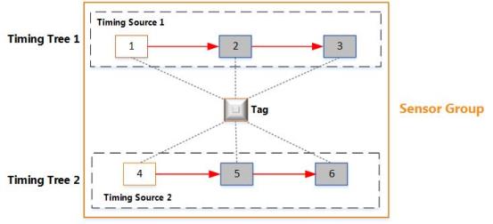
Multiple Timing Trees in the Same Group
The figure shows an example sensor group that has six sensors and two separate timing trees:
-
Sensors 2 and 3 receive timing signals from Timing Source 1. They are synchronized with each other and generate TDOAs.
-
Sensors 5 and 6 receive timing signals from Timing Source 2. They are synchronized with each other and generate TDOAs.
You do not need to synchronize sensors from different Sensor Groups.
Configuring Timing Sources
The sensor installation plan defines the timing sources and cabling for each group. Each group can have multiple timing sources and timing trees.
To set up a sensor as a timing source:
-
On the Configure timing tab, identify the sensor that must be configured as the timing source.
By default, all sensors are configured to receive timing signals through a cable.
-
Select the sensor that must be configured as a timing source. From the Timing drop-down menu, select Timing source.
-
Reboot the sensor, as described in Rebooting Devices.
You must reboot the sensor whenever you change the timing source.
The timing status of the sensor is updated. The sensor now only generates timing signals, which can be used by other sensors.
Configuring Timing Options for Sensors
Sensors can receive timing either through an Ethernet cable or a timing cable.
Receiving Timing through a Timing Cable
By default, a sensor is configured to receive timing through a timing cable.
On the Configure timing tab, choose the Receive from cable option from the drop-down list if either:
-
The sensor has been daisy-chained, where it receives timing signals from another sensor that is connected to the timing source.
-
The sensor receives timing signals directly from the timing source.
For information on configuring sensors and cables, see Ubisense Sensors.
Receiving Timing from a TDU
If you are using a TDU to distribute combined network and timing signals, you must change the timing configuration for the sensors.
To do this, on the Configure timing tab, change the timing status to Receive from ethernet.
Configuring Timing Sources for Use with TDUs
You can use a sensor to distribute combined network and timing signals through the Ethernet cable (connected to the Ethernet (PoE) port on the sensor) as shown in the following figure.

Hardware Configuration for Distributing Timing on the Ethernet Port
For this setup, change the timing configuration as follows:
- On the Change sensor parameters tab, select the sensor to use as the timing source.
-
Navigate to the Sensor > Physical > Timing > Allow Ethernet Output parameter.
The parameter has the following values:
- False: the sensor is configured for timing input only on the Ethernet port.
- True: the sensor is configured to send timing output on the Ethernet port, if it does not receive timing from this port.
-
Double-click Allow Ethernet Output and set the parameter as required:
- To configure the sensor for both timing input and output, select the checkbox.
- To configure the sensor for timing input only, clear the checkbox.
- Click Save.
Checking and Troubleshooting Timing Trees
You can check and troubleshoot timing trees only after the sensors have booted.
After you have set up timing sources and defined timing options for the other sensors in the group, check the timing trees to see how the timing signals are distributed.
On the Place devices tab, click Show view options, and then select Show timing tree.
Red arrows, which indicate timing signals, are shown on the sensor group:
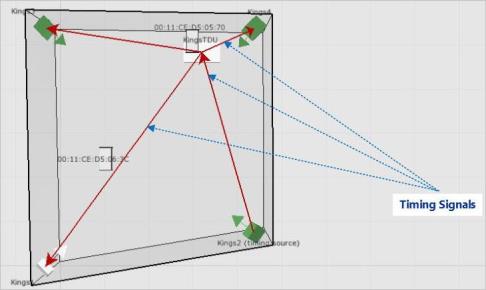
Sensor Group Showing the Timing Tree
The directions of the arrows show how the timing signals are distributed. Review the timing tree carefully to check that the timing signals are distributed, as expected.
If the arrows fail to appear or do not appear as you expected, check for any obvious issues, for example:
-
Check that you have set up correct timing sources and cabling options for sensors.
-
Check that the physical cables have been connected to the correct ports on the sensors, as described in Ubisense Sensors.