Adding and Placing Devices
You can add DIMENSION4 sensors, Timing Distribution Units (TDUs) and
Adding and placing devices involves:
- Adding each device by specifying its MAC address.
-
Creating one or more sensor groups to group the devices logically, and adding each device to the appropriate group.
Device Details Sensors
Create the required groups, and enter the location of each sensor. You do not need to enter the orientation of the sensors—the Solver will calculate this for you.
TDU
Automatically added to its own group. Enter the location.
2.4 GHz Receiver
Automatically added to its own group. Enter the location.
- Adding sensors to the appropriate groups.
- Positioning sensors.
Adding Devices
You can add a sensor or TDU to the D4 RTLS by either:
-
Typing its MAC address.
-
Scanning its MAC address from the barcode label.
Note: The D4 RTLS supports TDUs that have a MAC address starting with 00:11:CE:E4.
You can also add a discontinued 2.4 GHz Receiver by typing in its MAC address. The D4 RTLS supports 2.4 GHz Receivers that have a MAC address starting with 00:11:CE:D5.
Adding a Device using its MAC Address
To add a device by using its MAC address:
-
On the Place devices tab, add the required device. To add multiple devices, type the MAC address of each device on a separate line.
LSC automatically detects the type of device and places it in the correct group.
-
Save the MAC addresses that you have typed.
The device(s) appear on the following lists:
-
Ungrouped: The sensors currently do not belong to any group.
-
Unpositioned: The devices, whether sensors, TDUs or 2.4 GHz Receivers do not have a location.
-
Adding a Device by Scanning its Barcode Label
To add a device by scanning its MAC address from the barcode label on its back panel, you require a 1D Barcode Scanner.
To add a device by scanning its barcode label:
-
Connect the Barcode Scanner to your computer.
-
On the Place devices tab, double-click <Add new device>.
Make sure that the cursor is displayed in the box.
- Using the Barcode Scanner, scan the MAC address barcode label of the device.
-
The MAC address appears on the list of devices to be added.
-
Save the address that you have scanned.
The device(s) appear on the following lists:
-
Ungrouped: The sensors currently do not belong to any group.
-
Unpositioned: The devices, whether sensors, TDUs or 2.4 GHz Receivers do not have a location.
-
Naming Devices
The devices listed on the Place devices tab are listed by name if the name is configured, otherwise they are listed by MAC address.
To enter the name of each device, double-click the MAC address to display the editor.
A meaningful name can help you to identify the sensor more easily, particularly in large-scale installations.
We recommend that you add the last two HEX pairs from the MAC address to the sensor name. For example, PAINTSHOP_S1_01:54, which represents the first sensor that belongs to the PAINTSHOP area and has a MAC address 00:11:CE:D4:01:54.
Deleting a Device
You can only delete a device that is ungrouped.
To delete a device:
-
On the Place devices tab, select the device that you want to delete from the Ungrouped list, and then press the Delete key. The LSC tool prompts you to confirm that you want to delete the sensor.
-
Click Delete.
The device is deleted. It no longer generates location data or distributes timing.
In production systems earlier than version 3.6, it is recommended that you do not delete devices. Always swap them, using the Replace infrastructure tab, as described in Replacing and Removing a Device.
Working with Sensor Groups
In a D4 RTLS, the entire location tracking area is covered by one or more Sensor Groups. Sensors that belong to the same group can exchange data to locate a tag. Sensors from different groups cannot exchange data.
The size and number of groups that you must create depends on the requirements defined in your sensor installation plan.
Typically, groups are created depending on:
-
The size of the location tracking area. A small area might require one group with a small number of sensors, whereas a larger area might require multiple groups and more sensors.
-
The way in which you want to track your objects. For example, if objects are moving along a line, you can create overlapping groups, so that the sensors can track objects as they move from one area to another.
About Sensor Groups
A Sensor Group can cover multiple rooms. Sensors can belong to one or more groups.
An example Location Cell with three sensor groups, is shown in the following figure.
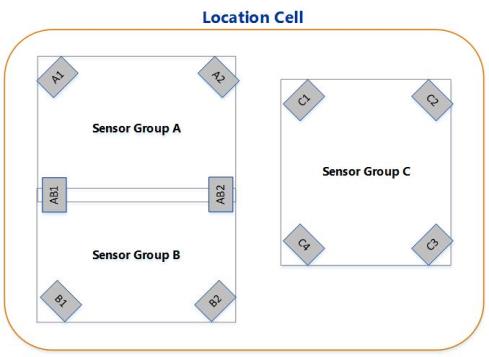
Sensor Groups
In the example:
-
Group A and Group B are adjacent to each other (and overlap). Sensors AB1 and AB2 belong to both Group A and Group B. Therefore, these two sensors can exchange data with the other sensors from both Group A and Group B.
-
Sensors A1, A2, B1, and B2 are not shared. Therefore, they cannot exchange any data between Groups A and B.
-
Group C is completely independent and does not share any sensors or exchange data with Group A and Group B.
A sensor group can overlap location cells. In cases where the sensors in a group are in more than one location cell, it is easy to determine which location cell to use when examining event logging data, because if an event has a valid location and that location is contained in some location cell then the corresponding location event will go straight to the cell server for that location cell, and the logging event will go to the logging server for that location cell. (Prior to D4 version 3.6, sensors sent data to the location cell they were in and the choice of sensor for a tag did not depend on the location of the tag.) If an event has no valid location, then its logging event is sent to the logging server that was used for the last event that did have a valid location (and its location event is not sent).
About Clipping Regions and Snap Distances
You can define a clipping region for a Sensor Group if you are only interested in the location events that are generated when tags are inside the area covered by the clipping region.
If required, you can also define a zone around the clipping region, called the snap distance. If a tag is detected inside the snap distance, it is considered to be inside a Sensor Group. Therefore, if a tag enters this zone, sensors can locate the tag even if it is not fully within the group.
As a sensor group represents a 3-dimensional space, you can configure both horizontal snap distance and vertical snap distance for your sensor group. The following figure shows an example for horizontal snap distance.
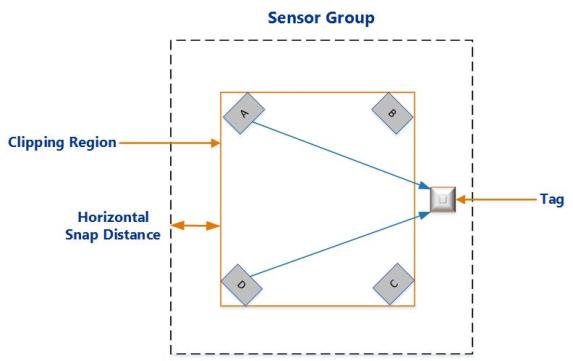
Horizontal Snap Distance
Creating Sensor Groups
To create a sensor group:
-
Click the Place devices tab.
-
Create a new sensor group. To create multiple sensor groups at the same time, type the name of each sensor group, one on each line of the box.
-
Click Save.
The new groups appear in the list of existing groups.
Defining a Clipping Region
You can optionally define a 2.5D clipping region for each group.
- Double-click the group.
-
Following the onscreen instructions, add points to define the 2D extent of the clipping region.
When you click and drag to add a point, the coordinates of the point are displayed. Use this information to place the clipping region within the Location Cell, allowing also for the snap distance that is in addition to the extent.
Notes:
- The clipping region can be any shape.
- If you want to share a sensor between groups that have a clipping region, then the clipping regions should overlap.
- If you have set up a background representation, you can use this as a guide when defining the 2D extent of the clipping regions.
- To view coordinates and additional features such as background representations, click Show view options.
-
Specify the height (top and bottom) of the clipping region in meters—this must be contained within the height of the Location Cell.
The floor of the clipping region must match the actual height of the floor in your physical environment. This floor height is used as a reference to specify the height range for tag filters, as described in Configuring Height and Speed.
-
Optionally, specify the horizontal and vertical snap distances.
Adding a Sensor to a Group
Each sensor must belong to at least one group. You can also add a sensor to multiple groups if you need to track the movement of a tag from an area covered by one Sensor Group into an area covered by another group.
To add a sensor to a group:
-
Click the Place devices tab.
- Do one of the following:
If the sensor does not belong to any group, it appears on the list of Ungrouped sensors. Select the sensor and then drag it into the required group.
If the sensor already belongs to a group and you want to share it with another group, press the Shift key, and drag and drop the sensor from one group to another group. The sensor is listed in both groups.
Positioning Sensors
Positioning a sensor in a group involves:
-
Specifying the precise X, Y, and Z coordinates of the sensor.
- Specifying the approximate pitch and yaw angles of the sensor.
This information is used to calculate tag positions.
Estimating Pitch and Yaw
When placing a sensor, you should specify the approximate pitch and yaw of the sensor. These values are then accurately measured and overridden when you run the Solver, as described in Solving Sensor Parameters.
Pitch
Pitch is the vertical angle of the sensor. Examples of a sensor positioned at a pitch of ‑41 degrees and ‑55 degrees, are shown in the following figure.
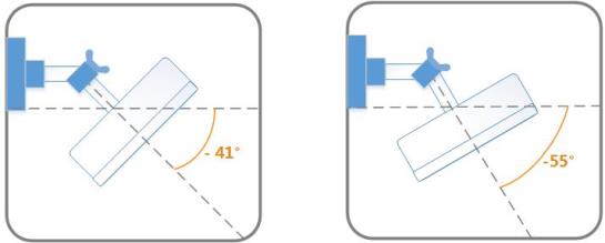
Sensor Positioned at Different Pitch Angles
Yaw
Yaw is the horizontal angle of the sensor, shown in the following figure.
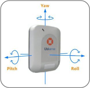
Yaw, Pitch, and Roll of a Sensor
Obtaining Sensor Positions
To calculate the position of a tag, you require the precise X, Y, Z coordinates of each sensor that belongs to the group.
These coordinates are measured with a Total Station and recorded after the sensors are installed.
To calculate the X, Y, Z coordinates of a sensor:
- Define a coordinate system.
- In your location tracking site, pick a point on the floor (origin) from which you can measure the coordinates.
- Decide which horizontal direction you want to use as the positive X-axis. Facing in this direction, the positive Y-axis is to your left, and the positive Z-axis is upwards.
-
Following the instructions supplied with your Total Station, measure the position of the fiducial mark on the front panel of the sensor.
Ensure that you:
- Measure both horizontal and vertical offsets to the sensor.
- Survey the positions of the sensor to an accuracy of better than 5 cms. If the surveyed positions are accurate, the Solver (part of Location System Config) returns more reliable sensor positions.
- Note down the coordinates for the X, Y, and Z axes, for example, add them to the Sensor Installation Plan.
Positioning the Sensor
Unpositioned sensors cannot generate location data. To generate location data:
- The coordinates of the sensor must be inside a Location Cell.
- The sensor must belong to a Sensor Group.
Sensors that do not have a location appear on the list of Unpositioned sensors (even if they already belong to one or more groups).
To position a sensor:
-
On the Place devices tab, double-click the MAC address or name of the sensor.
-
Define its position by specifying the location, yaw, and pitch.
Field Value Location
Type the X, Y, and Z coordinates with the values that have been calculated with a Total Station. Note that:
-
The coordinates must be inside a Location Cell.
-
You can drag the sensor from the Unpositioned list onto the map.
Yaw and Pitch
Type the estimated horizontal and vertical angles at which the sensor has been mounted or enter 0. For more information, see Estimating Pitch and Yaw.
-
Removing a Sensor from a Group
To remove a sensor from a group:
-
Expand the group from which you want to remove the sensor.
- Select the sensor, and then press the Delete key.
-
The sensor is removed from the group.
Note that the sensor appears on the list of Ungrouped sensors only if it does not belong to any other group.
Unpositioning Sensors
If you have already run the Solver then you must use the Replace infrastructure tab to invalidate the orientation results of any sensors that you unposition. You must do this before rerunning the Solver. See Replacing the Infrastructure.
To unposition a sensor:
-
On the Place devices tab, double-click the MAC address or name of the sensor that you want to unposition.
-
Select the Unset sensor position checkbox.
-
Save the settings.
The sensor still belongs to the group but it no longer has any coordinates, and therefore appears on the list of Unpositioned sensors.
- You can now reposition the sensor as required.
Deleting a Sensor Group
To delete a Sensor Group:
-
On the Place devices tab, select the group that you want to delete, and then press the Delete key. The LSC tool prompts you to confirm that you want to delete the group.
-
Click Delete.
The Sensor Group is deleted. If the sensors do not belong to any other group, they appear on the list of Ungrouped sensors.
Positioning Other Devices
You must set the position of TDUs as this ensures that they are displayed in the correct location on the background map.
A TDU does not need to be positioned in the same Location Cell as its sensors. You do not have to specify the orientation of a TDU as TDUs do not locate tags.
To position a TDU:
- On the Place devices tab, expand the TDU group.
-
Do one of the following:
- Double-click the TDU that you want to position, and then type its X, Y, Z co-ordinates.
- Drag the TDU to the map.
Ensure that you position the TDU within the extent of a Location Cell.