Configuring ACS installations in SmartSpace
From version 2.7 onwards, ACS was installed with SmartSpace in place of earlier Ubisense services. Where previously Ubisense Site Manager would have been used for some configuration of ACS, some of these activities were carried out using SmartSpace Config.
After you have installed ACS, configuration activities outside the ACS Main GUI are:
-
Creation of a Geometry Cell and Location Cell in SmartSpace
Adding cells to your site is described in Cells
-
Creation of ACS areas
-
Import of suitable graphics for use as models for ACS product types
ACS products can be viewed in the Place objects workspace in SmartSpace Config. Additionally, depending on the SmartSpace modules you have licensed, you can use ACS types in searches on the web map or in business rules.
Creating areas for use in ACS
In ACS, areas are used to partition the site model. Usually an area will represent some complete, but relatively self-contained region of the site, such as one floor of a building, or one functional area of a large floor. ACS areas can include walls which are used to create a simple visualization of the area's layout. Walls are defined in text files containing a list of coordinates for the start and end point of each wall in an area. To create an area with walls for use in ACS, you must first define the walls and then load them into a new area. The extent of the area is automatically created. After they have been defined, you can view the areas in the map views in ACS.
Command-line tools are available for working with walls and areas for ACS:
- ubisense_load_walls creates a new area with a given name with wall details read from a specified file
- ubisense_export_walls allows you to export existing wall data for an area for import into a different dataset
Other command-line tools enable you to import and export area data in .xbd format:
- ubisense_import_area_data allows you to import area data from a file into ACS
- ubisense_export_area_data allows you to export existing area data from ACS
You can download these tools using the Ubisense Application Manager where they can be found in the DOWNLOADABLES tab under Ubisense Generation 2.X > ACS > Tools.
Creating an Area with Walls for ACS
The following example shows how a file of co-ordinates that define the locations of a number of walls can be used to create an area for use in ACS.
The file walls-area-1.txt contains details of an area with each wall defined in a line of details containing a pair of (x,y) co-ordinates for the beginning and end of the wall:
-35.25 -32.25 -35.25 25.35
-35.25 -32.25 -2.6 -32.25
-35.25 -25.1 -35.25 25.35
-34.95 -31.95 -34.95 -25.3
-34.95 -31.95 -16.76 -31.95
The co-ordinates are calculated from the origin on your site map. You can specify an offset during area creation to shift the area and walls relative to the origin. The height of the area is also specified during this process.
To create a new area called Area-1 containing these walls with a vertical extent of 1.5 m, run the following command:
ubisense_load_walls create Area-1 "Area 1" 0 1.5 walls-area-1.txt
In the ACS Main GUI, you can now select the area for display in maps for example in the Edit Assembly Parameters dialog:

You can view the extents of imported areas in SmartSpace by using the Pull areas from Generation2.X button in the Spatial properties workspace:

Note: You cannot see the details of walls in SmartSpace.
After you have pulled details of ACS areas into SmartSpace Config you can edit their extents. You must then use the Push areas to Generation2.X button to propagate the changes to the ACS Main GUI. Similarly, if you edit areas extents in the ACS Main GUI and you want to see these changes in SmartSpace, you must use the Pull areas from Generation2.X button to ensure the details match.
You can also create ACS areas directly in SmartSpace Config and define their extents. However areas created in this way cannot have walls within them and are not visible in the ACS Main GUI. See Creating areas for use in ACS.
You can use the ubisense_load_walls command to list all areas whether imported or created in SmartSpace. For example, the three areas shown in the preceding screenshots are listed as follows:
Area-3 Generated by SmartSpace Config
Area-2 Area 2
Area-1 Area 1
Copying models for use in ACS
Importing models into ACS from SmartSpace
You can import 2D models into ACS from SmartSpace. Note, however, that the 3D view engine is not the same in ACS and SmartSpace and you cannot share 3D representations between SmartSpace and ACS.
When you want to use a representation in ACS, the original image size, in pixels, must be in terms of powers of 2. So, for example, a square image could be 256 x 256 or 512 x 512. Rectangular images can be, for example, 256 x 128 or 256 x 512. If the original images do not conform to this rule, then, although they appear as expected in SmartSpace, when they are imported into ACS the representations' origins may be shifted or their scaling distorted.
Note: If your image does not have dimensions that conform to the power of 2 rule, you could add transparent padding to the image to make it comply.
You import 2D models using the Model import workspace where you can select an image file for import and give it a name.
For any models you intend to associate with product types, you must include the suffix _template in their names.
To import an object representation:
- In SmartSpace Config click MODEL IMPORT to open the Model import workspace.
- Double-click <Import representation>.
- Navigate to the image file.
-
The filename, including its suffix, becomes the default name of the representation.
Edit the name ensuring that you add the suffix _template to the filename.
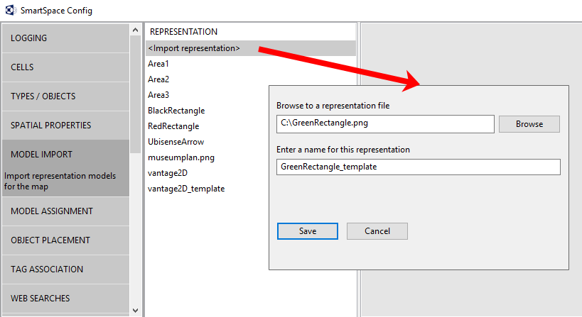
- Click Save.
-
You can now adjust the size and orientation of the representation, and set its origin to match the object it will depict.
See Model import on the SmartSpace website at http://www.ubisensesmartspace.com/ for further information on manipulating imported representations.
When you have imported the models you require, you can copy them to ACS.
Copying models to ACS
To copy 2D models to ACS:
- In SmartSpace Config, click MODEL ASSIGNMENT to open the Model assignment workspace.
-
Click the Copy 2D models to Ubisense Generation2.X programs button to display a list of 2D models to be copied.
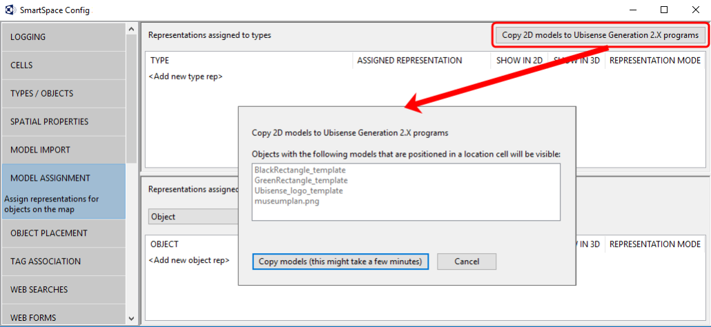
All objects listed in the dialog will be imported into ACS. However, only those whose names end in _template will be offered as representations when defining product types.
-
Click the Copy models... button and the files are copied to ACS.
When the operation is complete, the dialog closes and you are returned to the Model assignment workspace.
You can now use the templates when defining ACS Product types.
ACS types in SmartSpace
A number of ACS types are available in SmartSpace to which you can add properties and representations .
The following table summarizes ACS types and their properties in SmartSpace, and how you can use them is discussed below.
|
ACS type |
Description |
Spatial properties visible in SmartSpace |
Other properties visible in SmartSpace |
|---|---|---|---|
|
ACS Object |
Parent type for all ACS Object types. Not used directly. |
– |
ACS name Description Maintenance Mode Requested Maintenance Mode |
|
ACS Assembly Line |
Parent type for all ACS Assembly Line types |
– |
ACS name Description Maintenance Mode Path Requested Maintenance Mode Requested Reset Flag |
| ACS Assembly Point | Parent type for all ACS Assembly Point types | – | ACS name
Description Maintenance Mode Requested Maintenance Mode |
|
ACS Association Zone |
Parent type for all ACS Association Zone types |
– |
ACS name Description Maintenance Mode Requested Maintenance Mode |
|
ACS Device |
Parent type for all ACS Device types |
extent |
ACS name Deactivation Timeout Description Maintenance Mode Requested Maintenance Mode |
|
ACS Disassociation Zone |
Parent type for all ACS Disassociation Zone types |
– |
ACS name Description Maintenance Mode Requested Maintenance Mode |
|
ACS Event |
Parent type for all ACS Event types |
– |
ACS name Class Description Maintenance Mode Requested Maintenance Mode Timeout |
|
Outgoing ACS Event |
Parent type for all Outgoing ACS Event types |
– |
ACS name Class Description Maintenance Mode Requested Maintenance Mode Timeout |
| ACS Event Subscription | Parent type for all ACS Event Subscription types | – | ACS name
Description Maintenance Mode Requested Maintenance Mode |
|
ACS Exception |
Parent type for all ACS Exception types |
– |
ACS name Acknowledge Description Maintenance Mode Requested Maintenance Mode Text Time Type |
|
ACS External System |
Parent type for all ACS External System types |
– |
ACS name Actual Connection Status Connection Info Description Desired Connection Status IP Address Maintenance Mode Parameters Port Protocol Protocol Version Remote station is server Requested Connection Status Requested Maintenance Mode |
|
ACS Ident Zone |
Parent type for all ACS Ident Zone types |
preparation zone trigger zone |
ACS name Description Maintenance Mode Requested Maintenance Mode |
|
ACS Product |
Parent type for all ACS Product types |
– |
ACS name Description Maintenance Mode Requested Maintenance Mode Requested Tag Position and Group Tag Position and Group Tag Position Options |
| ACS Production Line | Parent type for all ACS Production Line types | – | ACS name
Description Maintenance Mode Requested Maintenance Mode |
|
ACS Station |
Parent type for all ACS Station types |
extent |
ACS name Description Maintenance Mode Owner Requested Maintenance Mode |
|
ACS Trigger Point |
Parent type for all ACS Trigger Point types |
– |
ACS name Description Maintenance Mode Offset Owner Requested Maintenance Mode |
|
ACS Workspace |
Parent type for all ACS Workspace types |
extent |
ACS name Description Maintenance Mode Requested Maintenance Mode |
|
ACS SmartSpace Object |
This is a parent type to group ACS types in SmartSpace Config. Not used directly. |
– |
– |
|
ACS Object Lifecycle |
Parent type for all ACS Object Lifecycle types |
– |
Description Requested Creation Parameters |
|
ACS Product Space |
Parent type for all ACS Product Space types |
– |
Description |
|
ACS Product Type |
Parent type for all ACS Product Type types |
– |
Description |
You can use SmartSpace Config to create properties for ACS types. However, there are limits to what you can do with ACS types:
- You must not create types based on any of the ACS types.
- You must not create or rename ACS objects using SmartSpace Config.
- You must not create properties that are ‘used as the name of the type’ for ACS types.
Extents of ACS types
SmartSpace Config will show spatial properties automatically for ACS Device, ACS Ident Zone, ACS Station, ACS Workspace types and you can edit them in the Spatial properties workspace. Do not delete any object-specific spaces in SmartSpace because ACS may then delete the object entirely.
ACS Product spaces are not visible in SmartSpace, and any space properties you add to ACS Products in SmartSpace Config will not be visible in the ACS Main GUI.
Searches using ACS types
If you have licensed the Visibility component of SmartSpace, you create searches to use with the web map and web forms for display in a browser. When creating a search for an ACS type, it is based on the ACS name property. For example a search for ACS Products would be defined in the Web searches workspace as shown below:

Using the Requested Connection Status property with ACS External Systems
The ACS External System type has a number of properties whose values can be seen in SmartSpace. However, with one exception, you cannot set these values in SmartSpace. If you attempt to do so they will change back to the real values from ACS. The special case is the Requested Connection Status which you can set to one of three permitted values:
- Connected
- Disconnected
- Restart
This value is sent to the Desired Connection Status in ACS. If you have the Visibility component licensed, you can create a web search and a web form that allows users to connect or disconnect external systems.
Synchronizing SmartSpace properties and ACS product parameters
ACS product parameters can be pushed into SmartSpace properties by following these steps:
-
Identify the property to sync in the ACS Main GUI.
Go to Operation > Product Instances and click Show parameters. Select a product and any parameters associated with it are listed.
-
Create a corresponding property in SmartSpace Config.
In the Types and objects workspace, select the ACS type in the upper part of the types and properties list. Double-click <Create new property> and enter the details of the property.
-
Set up the transfer process with the ubisense_acs_smartspace_sync_admin tool.
You can get the ubisense_acs_smartspace_sync_admin tool using the Application Manager where you can find it in the DOWNLOADABLES tab under Ubisense Generation 2.X > SmartSpace backwards compatibility with ACS > ACS SmartSpace sync admin tools.
The command-line usage is as follows:
ubisense_acs_smartspace_sync_admin.exe create <property> <type> <internal>where:
- <property> is the name in the ACS Main GUI Product Instances screen
- <type> is the type of object that has a value for the parameter
-
It is the internal name of the type, which must inherit “ACS::Physical”
For example, “ACS::Physical” and “ACS::Product” are both valid and user-defined product types prefixed with “ACS::” are also valid
- <internal> is the internal name of the the SmartSpace property, for example [Custom]sequence_number<ACS::Product>
Adding Extents for ACS Devices in SmartSpace
If you need various hysteresis values, you can use SmartSpace Config to configure multiple extents using different spatial property names, and you can then select them in the ACS Main GUI. The steps to take are summarized below. See Types and objects and Spatial properties for further information on configuring types and their spatial properties in SmartSpace Config, and the section on Devices
To configure additional non-default extents for ACS devices:
In SmartSpace Config:
-
In TYPES / OBJECTS, create a new property of type "Space" for the ACS Device type or any of its descendants:

-
In SPATIAL PROPERTIES, create a default space for the property you just created:

-
In the Device Instances dialog, choose the space you just created from the Space dropdown:

-
Depending on your workflow and how this is done across multiple datasets, changing the default extent might be confusing, so always consider giving non-default extents a suitable property name.
In the ACS Main GUI
Displaying the ACS tag representation in SmartSpace
In ACS, tags are displayed using a green representation. To enable the same default representation in SmartSpace, for example to be visible in the Place objects workspace, download and run the ubisense_toggle_v2_tag_rep tool.
Download the tool using Ubisense Application Manager. You can find the ubisense_toggle_v2_tag_rep tool by choosing the DOWNLOADABLES tab and going to Ubisense Generation 2.X > ACS > Tools. Select the ubisense_toggle_v2_tag_rep tool, click Download selected items and then choose your download location and click Start download.
To switch the default representation on, use the following command:
ubisense_toggle_v2_tag_rep on