Spatial properties
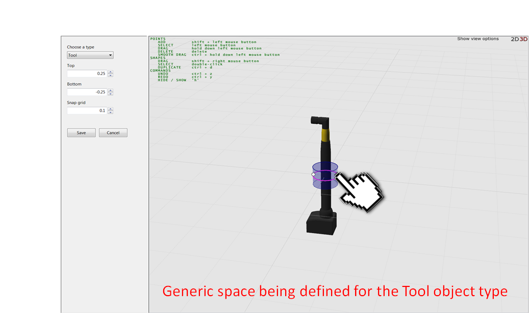
A generic space is one which is assigned generically to an object type and which exists for every instance of that type. The space is “attached” to the object, in that its position relative to the origin of the object is fixed, and as such when the object moves the space moves by exactly the same amount as well. This is known as a relative space in SmartSpace. An example of such a space is shown below, where a trackable hand tool has a cylindrical generic space attached.
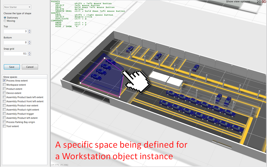
The alternative to a generic space is a specific space. This is a space definition which is unique to an object instance of a particular type. Specific spaces can be both stationary (they are fixed to a specific location in the world model) or relative (much like generic spaces, they move relative to the object location). An example of a stationary specific space is a geofence that represents a physical workspace or footprint in a factory. Such physical workstation footprints will be different in size, position and orientation across the factory, so a specific space is required to capture the uniqueness of each space. In this case you would need an instance of a type called “workstation” in your object model with at least one Space property defined. You can then define a specific space for that object for the workstation, such as in the example shown below.
The Spatial properties workspace
The Spatial properties workspace in SmartSpace Config provides tools to create, edit and delete spatial properties and to create spatial relations.
Click on SPATIAL PROPERTIES to display the workspace.

Details of types and spaces
In the Details of types and spaces area, you can select a type and an associated space property. Only types with space properties are listed in the <Select a type> dropdown and only space properties are listed for them at <Select a property>.
The lists below show details of default and specific spaces that have been defined.
To view an existing space, select a type and a space property, then a default or specific space, and then click View Space. To edit a space, select the property in the default spaces or specific spaces list and click Edit Space (or double-click the name of the property).
Spatial property editor
The Spatial property editor displays the representation associated with the selected type. Click Show view options to configure the features the editor displays.
Spatial relationship editor
The Spatial relationship editor displays details of any monitored spatial relations and the service that requested it. The list contains spatial relations defined for particular SmartSpace features and also those you define (the latter are shown as requested by SmartSpace Config ).
Double-clicking <Add new request> allows you to define new spatial relations.
Configure space properties of types
When you have a type with a space property defined (described in Creating a custom type and adding a space property) and which has a default representation set (described in Adding a representation to a type) you can configure the volumetric values for its extent.
Open the Edit spatial properties workspace and decide whether you want to define a generic or a specific space. In the example below we’ll present the process for a generic space, but the process is much the same for specific spaces.
-
Choose a Type from the dropdown for which you wish to define a generic space, then select the space property you wish to edit and double-click the <Create new default space> option.

-
Ensure that your object type is selected from the dropdown and press Home to enter the editor view around your object representation.
Use the prompts overlaid on the screen to help you move and orient your view to best match the space extent you’re trying to define.
-
Hold down the Shift key and left-click in the editor view to set the first point of your extent. Repeat this to begin creating a space around the object. By default, two points define a cylinder and three or more points define a multi-sided polygon.

-
Modify the extent to meet your requirements. Some editing tips follow:
- At any time you can move a node of the extent by left-clicking the node to select it and left-dragging the mouse.
- You can delete a node at any time by left-clicking the node to select it (it will be highlighted red) and pressing Delete.
- You can move the whole space by pressing the Shift key on your keyboard and right-click dragging the space with your mouse
- It is often easier to define the horizontal extent of the object using a top-down (or 2D) view. You can toggle between 2D and 3D views using either the number keys on your keyboard (2 and 3) or clicking on the 2D 3D text in the editor view.
-
Ensure the vertical extent (height) of the space is set appropriately for your application.
For small, mobile objects whose height (as reported by a tracking system) is likely to vary quite a bit, we recommend that you center the vertical extent to form a somewhat flat cylinder around the object. This has the effect of making spatial monitoring for this class of object a 2D containment evaluation, which is good when the height of the object can vary quite a bit and it is really the interaction in the X/Y plane that is most interesting for business applications.

When defining the extent for a stationary space (one that is static in the world model) it is important to ensure that the vertical extent is both high enough (to account for variations in tracked height of objects moving in and out of these spaces) and low enough (it is possible to get a tracked height for objects that is below the ground plane. In this case, give stationary spaces a generous ceiling value and a slightly negative floor value).

Configure spatial relationships between types
To define a new spatial relation between two objects:
-
In the Spatial relationship editor double-click <Add new request>.

- Choose a container object and a contained object from the lists of objects with defined spatial extents.
- Click Save to save the relationship.