Ubisense 2.4 GHz Receivers (UBIPRES24) (discontinued)
2.4 GHz Receivers (UBIPRES24) are no longer supplied by Ubisense.
From DIMENSION4 version 3.5 onwards, certain DIMENSION4 sensors can receive GPS signals from tags, and associated DIMENSION4 support services can be configured to handle these signals. See
Ubisense2.4 GHz Receivers are listening devices that detect narrow-band 2.4 GHz transmissions from Ubisense Multi-mode Tags transmitting their GPS position which are used by the DIMENSION4 Real-time Location System to find the location of assets when they are out of range of the UWB Sensors.
Each receiver must be connected to one or two external antennas (not supplied). The type of antenna will depend on the radio coverage you require, such as omnidirectional antennas for broad coverage around the receiver, or directional antennas for more focused coverage in a particular direction. The antenna can be connected directly to the 2.4 GHz Receiver, or via a coaxial cable link up to 30 meters in length.
The 2.4 GHz Receiver operates within an Ethernet environment, using standard network infrastructure, such as Ethernet switches and Cat5e structured network cabling for communication between the receiver and servers. Receivers are powered over the network cabling using Power-over-Ethernet switches only.
Features on the Front Panel
The features of a 2.4 GHz Receiver are shown in the following figure.
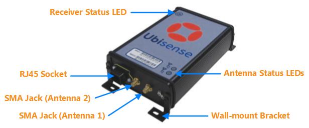
Front Panel of a 2.4 GHz Receiver
| Feature | Description |
|---|---|
|
Receiver Status LED |
The LED indicates activity on the receiver chip. It does not show activity on the antenna. |
|
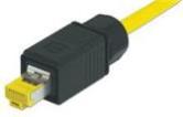
RJ45 Socket |
Supplies both network and power to the receiver. You can connect it to a Power-over-Ethernet (PoE) switch or to a PoE injector if a PoE switch is not available. The socket requires a HARTING PushPull RJ45 connector, order code 09 45 145 1561, as shown below:
|
|
SMA Jacks |
You can connect one or two antennas (not supplied) to the receiver, either directly connected to the receiver or connected via a coaxial cable link (maximum cable length 30m). The SMA jacks have separate MAC addresses. Although there are two MAC addresses, the 2.4 GHz Receiver has a single IP address. The SMA Jacks are also labeled on the back panel of the unit as Ant. 1 and Ant. 2. |
| Antenna Status LEDs | The antenna LEDs indicate activity on the relevant SMA jack. |
|
Wall-mount Brackets |
4 wall-mount brackets, sized for M4 screws. |
The enclosure of the 2.4 GHz Receiver meets the IP65 standard. If you require additional protection, mount the unit inside another box.
Features on the Back Panel
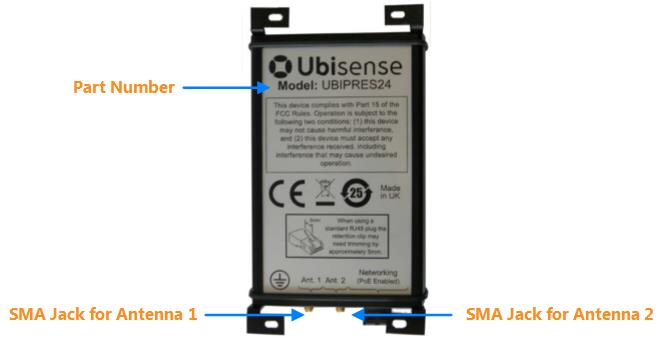
Back panel of a 2.4GHz Receiver
| Feature | Description |
|---|---|
| Part number |
The part number of the DIMENSION42.4 GHz Receiver. The Presence Sensor (for use with Series 7000 and Series 9000 Sensors) and the DIMENSION42.4 GHz Receiver have the same part number. The MAC address of a DIMENSION4 compatible receiver has the format 00:11:CE:D5:xx:xx where D5 indicates the unit is DIMENSION4 compatible. |
| Ant. 1, Ant. 2 |
Labels the SMA Jacks for antenna 1 and 2. |
Next Steps
Fit the required antenna to each 2.4 GHz Receiver and mount the receiver.
You can then:
-
Connect a network cable to each receiver.
-
Add the receivers to your D4 RTLS.
Connecting 2.4 GHz Receivers to the Network
You must connect each receiver by standard 100BASE-TX Ethernet to a Power-over-Ethernet (PoE) switch, which is also connected to the Location Platform server.
Network cabling for a receiver and the Location Platform server, through a PoE network switch, is shown in the following figure.
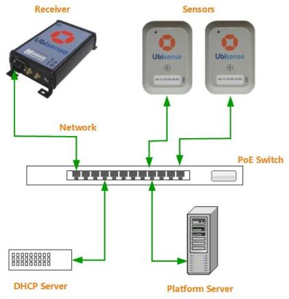
Network Cabling for Receivers
Configuring 2.4 GHz Receivers
2.4 GHz Receivers (UBIPRES24) are no longer supplied by Ubisense.
From DIMENSION4 version 3.5 onwards, certain DIMENSION4 sensors can receive GPS signals from tags, and associated DIMENSION4 support services can be configured to handle these signals. See
Prerequisites
You must install the following:
- GPS Support services
- GPS Configuration tool
- Location System Config (to define Location Cells)
The GPS Configuration tool will start only if there is an existing Location Cell.
Installing GPS Support
This section describes how to install the additional services and license required if you want to track assets by GPS locations with 2.4 GHz Receivers and Multi-mode Tags.
Distribution Zip
Do not copy or extract the files to Ubisense 3/bin because the zip contains DLLs which may overwrite DLLs required by other Ubisense software.
The GPS Support distribution, UbisenseGPS_x_x_x_xxxx.zip (where x_x_x_xxxx represents the version of the software), contains the components listed in the following table:
| Components | Details |
|---|---|
|
Firmware |
The version 1.0.15 firmware for 2.4 GHz Receivers. Contact Ubisense Support for further information on the version of the firmware in your 2.4 GHz Receivers and how to upgrade it. |
|
Packages |
The Ubisense GPS services for using D4 RTLS with GPS on either a Windows or Linux server. |
|
Setup |
The installer for the UbisenseGPS Configuration tool tool (Windows only). This is compatible with DIMENSION4, Series 9000 and Series 7000. Before installing the GPS Configuration tool tool, uninstall any previous versions from the machine on which you intend to run the tool. This includes any GPS Configuration tool tools installed as part of a Series 7000 system or a Series 9000 system. |
Extract UbisenseGPS_x_x_x_xxxx.zip to a new folder. For example:
Installing GPS Support Services on Windows
To install the GPS Support services:
- Run Service Manager 3.
- Click on INSTALL SERVICES.
-
Specify the directory from which to install.
This is the packages directory in the folder into which you extracted the GPS Support distribution.
-
Select Everything (no feature dependencies found) and click Install.
- When installation is complete, click Close to close the Installing Services dialog.
To verify that the service is installed:
- In Service Manager, click on MANAGE SERVICES.
-
In the SERVICES pane, expand All/Ubisense Generation 2.X/Series 7000 RTLS and check that the folder contains the following services:
- GPS configuration
- GPS injector
Installing GPS Support Services on Linux
To install the GPS Support services on a Linux server, run the following command:
You can also install the services via a Windows client that is connected to the Linux server.
Installing the GPS Configuration Tool (Windows Clients Only)
Before installing the GPS Configuration tool tool, uninstall any previous versions from the machine on which you intend to run the tool. This includes any GPS Configuration tools installed as part of a Series 7000 system or a Series 9000 system. The new tool is compatible with DIMENSION4, Series 7000 and Series 9000.
To install the GPS Configuration tool.
- Navigate to the setup directory in the folder into which you extracted the GPS Support distribution.
- Double-click the UbisenseGPSConfigurationClient.msi file. The installer runs immediately and installs the tool. No dialog is displayed.
- Verify that the tool is installed. On the Windows Start menu, check that there is a Ubisense 2.1> Ubisense GPS Configuration command.
Configuring GPS for use with DIMENSION4
When using GPS with DIMENSION4, it should be noted that the GPS services do not support the 64‑bit D4 (GPS) Tag IDs.
To resolve this issue:
-
Using the ubisense_configuration_client command-line tool, set the following parameter:
ubisense_configuration_client set enable_gps 1 -
Set the configuration parameter gps_tag_id_hex_prefix to define the 32-bit prefix which is added to the 32-bit Tag ID produced by the GPS services, resulting in the required 64-bit (D4) Tag ID.
For example:
The D4 (GPS) Tag 00:11:CE:00:01:23:45:67 is processed by the GPS services as 01:23:45:67. If you define the gps_tag_id_hex_prefix as 0011ce00, this is combined with the 01:23:45:67 to produce the required 64-bit Tag ID 00:11:ce:00:01:23:45:67, which matches the Tag ID of the D4 (GPS) Tag being used.
The configuration parameter is set using:
ubisense_configuration_client set gps_tag_id_hex_prefix 0011ce00
Adding 2.4 GHz Receivers
Using LSC, add each receiver to the D4 RTLS.
On the Place devices tab:
-
Add the receiver to the D4 RTLS by typing in its MAC address.
The 2.4 GHz Receiver is automatically added to the group called 2.4GHz Receivers.
-
Position the receiver inside the appropriate Location Cell. The position of the receiver should be the position of the body of the receiver rather than the antenna(s).
The position should be reasonably accurate because the configurable Detector radius is derived from this position.
You do not need to set the yaw and pitch.
On the Configure 2.4GHz receivers tab:
- For the antenna in use on the receiver, select the Enable Radio checkbox.
Testing 2.4 GHz Receivers
Test that the 2.4 GHz Receiver works:
- In LSC, on the Configure 2.4GHz receivers tab, select the Sighting Trace checkbox for the antenna in use.
-
Check the log for sighting messages.
Any tags transmitting their GPS location should be seen (provided that Multi-mode Tags are in range and there is an antenna on the input port of the receiver).
- When you are satisfied that the receiver is working, clear the Sighting Trace checkbox to avoid excessive logging.
Configuring GPS Settings
You need to configure the GPS settings using the GPS Configuration tool. Before you can do this, you need to:
- Choose two outdoor reference points. These should be as far apart as possible as this improves the accuracy of the GPS results.
- Obtain the latitude and longitude of the outdoor reference points.
- Obtain the corresponding XY coordinates of the outdoor reference points relative to the origin of your D4 RTLS coordinate system.
To configure the GPS settings:
- Start the GPS Configuration tool from the Windows Start menu.
-
On the General tab, enter the following information for the two outdoor reference points (Point 1 and Point 2):
Setting Value Latitude, Longitude
Enter the latitude and longitude in decimal degrees, where North is a positive value and South is a negative value.
You can obtain this from a map or hand-held GPS system.
X Coordinate, Y Coordinate
Enter the X and Y coordinates, in meters from the origin of your D4 RTLS coordinate system.
You can obtain these using any of the following methods:
-
Linear measurements using a Total Station or tape measure
-
GPS receiver readings
Data derived from hand-held GPS Navigation systems may be inaccurate as these devices are designed to locate the position of a moving vehicle rather than a fixed, stationary point. -
Google Earth data
Data derived from Google Earth may be inaccurate. Aerial photographs are not always taken from directly overhead so it can be difficult to accurately establish the location of a vertical wall of a building. The images may also be distorted.
-
-
Enter the following configurable settings:
Setting Value Height
1
This is the default height (in meters) for the injected locations.
Earth Radius
6371000
This is an average radius (in meters) that you do not need to change.
Detector Radius
Locations are calculated for Multi-mode Tags detected within this distance (in meters) from the 2.4 GHz Receiver. Tags at a greater distance will be ignored and their GPS location data discarded.
Since the position of the 2.4 GHz Receiver recorded in LSC is the body of the receiver rather than the position of the antenna, the detector radius must be large enough to fully contain the area covered by the antenna (or both antennas if two antennas are connected to the receiver).
Location Cell
The Location Cell in which the 2.4 GHz Receiver is located.
-
Enter the remainder of the settings exactly as given below.
Setting Mandatory Value Position filter MedianCluster Inject Position Select the Inject Position checkbox—a check mark should be displayed. Tag decides jitter Select the Tag decides jitter checkbox—a check mark should be displayed. We recommend that you do not change these values. -
On the Filter Properties tab, enter the values for the MedianClusterFilter exactly as given below.
MedianClusterFilter Settings Mandatory Value Median Filter length 11 Mean Filter Length 1 Reset Median Filter Length 3 Reserved for future use 0 Enter 0 even though this setting is not used.
We recommend that you do not change these values..
Example
The recommended values for configuring a 2.4 GHz Receiver are shown below:
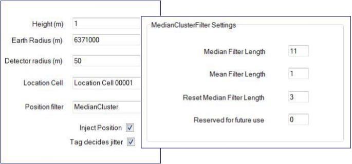
Recommended Settings in the GPS Configuration Tool
Testing GPS Location Tracking
To test the GPS functionality of the D4 RTLS you will need:
- a Multi-mode Tag with a clear view of the sky, within range of the receiver.
- a 2.4 GHz Receiver with a clear view of the Multi-mode Tag.
To set up the test:
-
Using the ubisense_configuration_client command-line tool, set the following parameter:
ubisense_configuration_client set enable_gps 1 -
Make a note of the current setting of the platform_monitor parameter—you will need to restore this setting later. Then add the following values to the current setting:
ubisense_configuration_client set platform_monitor <current_settings>:GpsPos:GpsDebug:GpsFilt:GpsTag - Restart all services.
-
In LSC, on the View trace messages tab, you should see messages with the prefixes:
GpsTagGpsDebugGpsFiltGpsPos
It may take some time before the messages appear depending on the GPS measurement interval of the Multi-mode Tag.
-
After testing, set the platform_monitor parameter back to its original value.
- Restart all services.
Troubleshooting
If GPS messages are received but you see locations being rejected:
- Check whether the location is incorrectly discarded because of the setting of the Detector radius parameter. The Trace log will tell you if this is happening.
- Check that the conversion from Latitude/Longitude values to XY values is as expected.