Ubisense 2.4 GHz Detector Sensors (D4DETECTOR32IP30)
Ubisense 2.4 GHz Detector Sensors are listening devices that detect narrow-band 2.4 GHz transmissions from Ubisense Multi-mode Tags transmitting their GPS positions. The DIMENSION4 Real-time Location System uses these transmissions to find the location of assets that are outside the range of standard UWB Sensor coverage.
Each receiver must be connected to one or two external antennas (not supplied). The type of antenna will depend on the radio coverage you require, for example omnidirectional antennas for broad coverage around the receiver, or directional antennas for more focused coverage in a particular direction. The antenna can be connected directly to the detector sensor, or via a coaxial cable link up to 30 meters in length.
The 2.4 GHz Detector Sensor operates within an Ethernet environment, using standard network infrastructure, such as Ethernet switches and Cat5e structured network cabling for communication between the receiver and servers. Detector Sensors are powered over the network cabling using Power-over-Ethernet switches only.
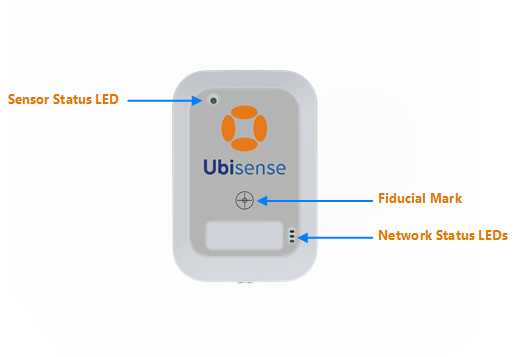
Features on the Front Panel
The features on the front panel of a UWB Sensor, are shown in the following figure.

Front Panel of a Detector Sensor
| Feature | Description |
|---|---|
|
Network Status LEDs |
The three LEDs show the network status and indicate that the sensor is receiving and transmitting network signals.
|
|
Sensor Status LED |
Shows the status of the sensor. |
|
Fiducial Mark |
Indicates the center of the sensor when recording the actual position of the mounted sensor using a Total Station. |
Features on the Back Panel
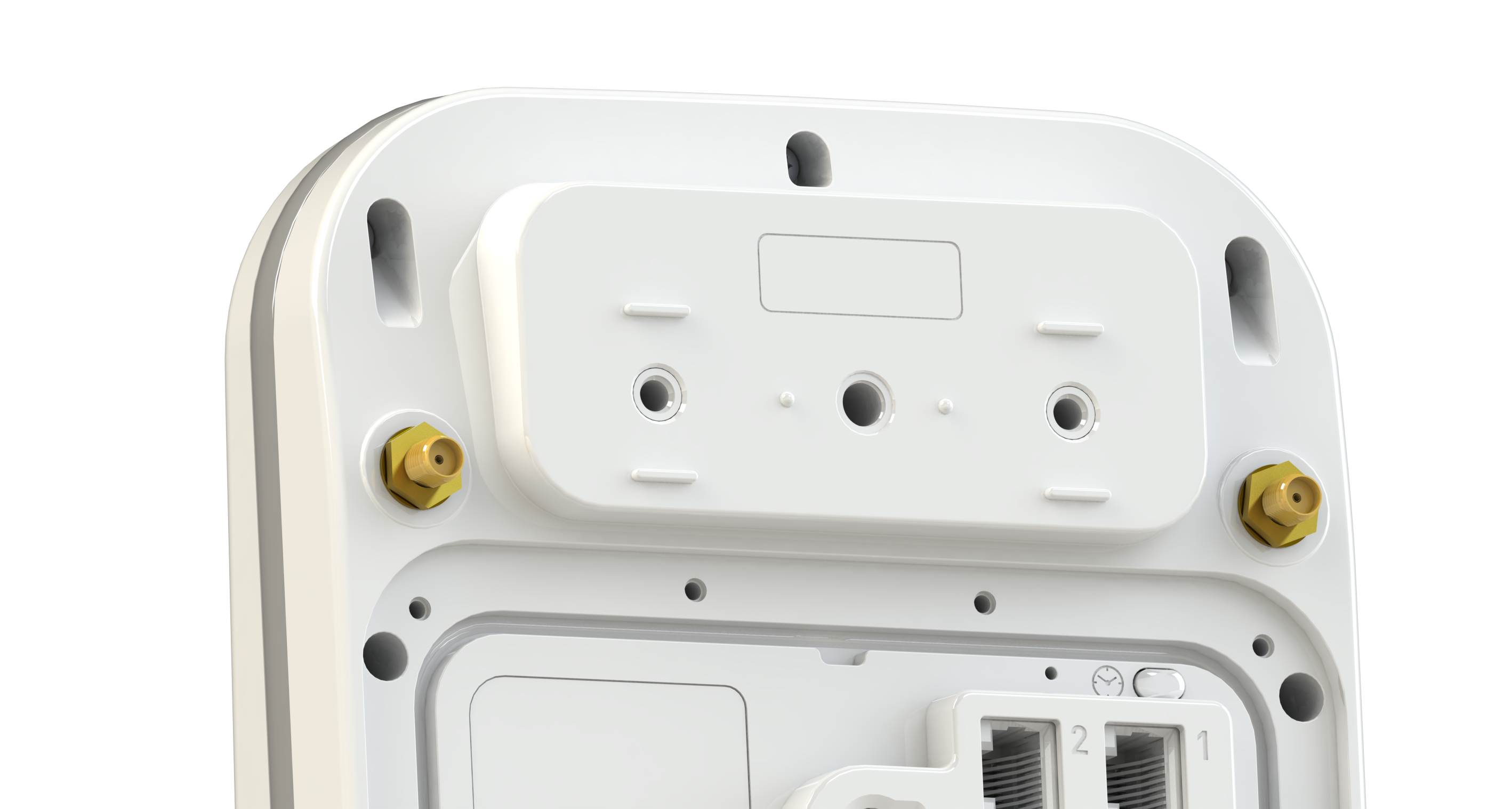
The features on the back panel of detector sensors are identical to those on the rear of directional sensors with the exception of the two SMA jacks for the connection of one or more external antennas, shown below.

SMA Jacks on the Back panel of a Detector Sensor
| Feature | Description |
|---|---|
| SMA Jacks |
You can connect one or two antennas (not supplied) to the receiver, either directly connected to the receiver or connected via a coaxial cable link (maximum cable length 30m). The SMA jacks have separate MAC addresses. Although there are two MAC addresses, the 2.4 GHz Receiver has a single IP address. |
Fitting Antennas
Mounting the Detector Sensor
Fit the required antenna to each detector sensor and mount the receiver.
Connecting 2.4 GHz Detector Sensors to the Network
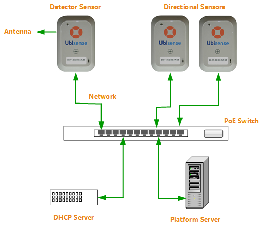
You must connect each detector sensor by standard 100BASE-TX Ethernet to a Power-over-Ethernet (PoE) switch, which is also connected to the Location Platform server.
Network cabling for a detector sensor and the Location Platform server, through a PoE network switch, is shown in the following figure.

Network Cabling for Detector Sensors
Next Steps
You can now Add the receivers to your D4 RTLS.