Ubisense Architecture and Protocols
Introduction and key principles
Ubisense SmartSpace and DIMENSION4 products are built using the same architecture that has been in use in large-scale installations for over a decade. As a result, the underlying protocols and techniques have been proven in many different environments on various computing platforms. This section explains the principles behind Ubisense operation, focusing on SmartSpace, by describing:
- the underlying architecture of a Ubisense system, the protocols it uses, how a system is decomposed into components, and how components are mapped onto processing units
- the most important services within SmartSpace, their role and usage
- how operational management of SmartSpace is done
- the SmartSpace Visibility component, how it uses web protocols, and the relevant security considerations
- how SmartSpace supports various use cases relating to scalability and multi-site operation
The key principles underlying the SmartSpace and DIMENSION4 architectures are as follows:
Homogeneity
All Ubisense data is managed using the same basic unit (the schema), and all schemas manage data using the same underlying mechanisms. This means that system test, management and optimization just requires that the maintainer test and optimize one kind of thing.
Dynamic Binding
Schemas are located using a simple discovery protocol that ensures that data consumers will transparently rebind to schemas when they are restarted, upgraded or migrated between machines.
Asynchronicity
Synchronization between processes is kept to the minimum possible level: consumers use locally-cached data to eliminate contention for data; cached data is updated using an asynchronous protocol; and remote operations may optionally be asynchronous.
Modularity
Schema data can only be changed by external agents using well-defined remote operations interfaces, ensuring that contracts are clearly defined and schema implementations are replaceable.
Low Latency
Data consumers in real-time location-driven control systems typically evaluate some kind of variably-complex query triggered by one of a number of events. Ubisense consumers use locally-cached data, ensuring that the data that they need is present in their address space when they need it.
Elasticity
Ubisense systems can run on one or many machines, and because Ubisense schemas can be migrated seamlessly, processing resources can be added at runtime. The combination of dynamic binding, asynchronicity, and local caching means that it is easy to run multiple copies of data consumers (e.g. web map, search support), so new instances can be added at runtime to support increasing user activity.
Service and protocol architecture
Schema Services
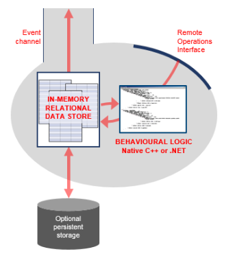
The diagram below shows a view inside a typical schema implementation, showing the data store, reliable multicast event channel, persistence layer, remote operations interface and behavioral implementation code.
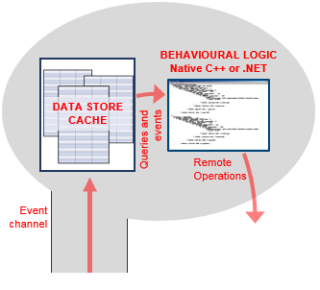
Schema Clients
Processes and Cross-schema Synchronization
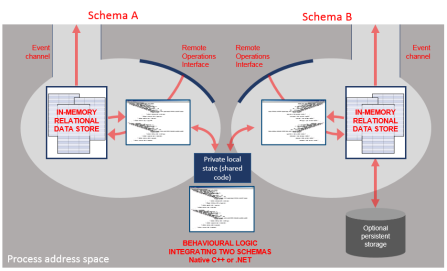
In general, arbitrary numbers of schema clients and servers can be used within one address space.
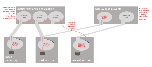
Building Applications – An Example
Protocols
Configuration Protocol
The configuration protocol is used by all Ubisense processes to establish parameters relevant to the other protocols which they will be using. For example, whether to use unicast or multicast IP for the operation of the system, the multicast port to use for service finding protocol requests, and other details relevant to overall system operation.
The configuration server is contained in the core Ubisense server
- If we are in unicast cluster mode, each of the addresses in the cluster
- The address given by the DNS entry ubisenseconfig
- The local host
- The broadcast address on the local subnet
The general configuration procedure uses a combination of local and networked data. The sources of configuration parameter values, from the highest to the lowest priority, are:
- Any file called platform.conf in the folder where the running executable is located
- Global parameters from the core server and retrieved by this configuration protocol
- The registry key
- A machine-level file platform.conf located in a central folder on the machine that the service is running on (by default on Windows: <installdir>\bin, on Linux: /etc/ubisense)
- Default values built into the executables
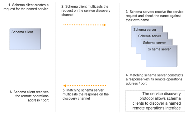
Service Finding Protocol
Service finding uses a simple discovery protocol that uses the same underlying multicast abstraction as the event channel protocol. This protocol supports discovery of an IP address and port number for the remote operations interface of a named service.
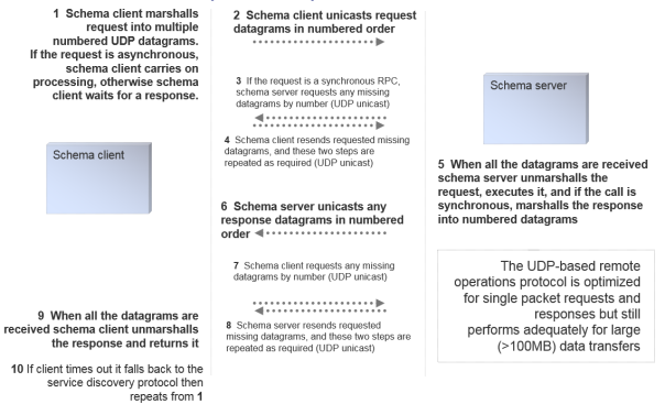
Remote Operations Protocol
The remote operations invocation protocol is built on top of UDP unicast. The protocol supports reliable synchronous RPCs, and also supports unreliable RPCs that are fully asynchronous, generally involving a single IP packet send.
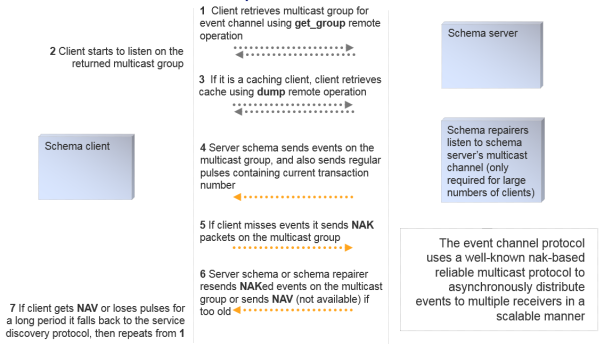
Event Channel Protocol and Schema Cache Update
The event channel protocol uses SRM (http://www.icir.org/floyd/papers/srm_ton.pdf), a well-known reliable 1:N protocol that scales well for the distribution of events to consumers. When well-tuned in a low packet loss environment, this protocol is as efficient as an unreliable multicast channel, but it also supports a NAK-based extension that guarantees reliable delivery and packet labeling that guarantees in-order delivery.
SRM relies on an abstraction of an underlying multicast transport. In a Ubisense system, this can be configured in one of three modes, selectable at runtime:
- Using IP Multicast, where one or more event channels can be assigned to a fixed multicast group. This approach is the easiest to manage and works well for systems spread across a large set of machines, but is not always supported by IT department policies.
- Using a (small) nominated set of N unicast addresses, where multicast sends are simulated by N separate unicast addresses. This approach works well for clusters of up to around a dozen machines. Very often this mode is used with N = 1, implementing a Ubisense system that runs on one single server.
- Using ‘standalone’ mode, where event channels are mapped to the localhost broadcast address. This mode is generally used for configuration and informal test of non-production systems, where the configuration user will run the test system on their personal machine.
The schema cache update process uses a combination of the remote operations protocol and the event channel protocol. When a schema client starts:
- It uses the service finding protocol to discover the IP address/port of the required schema service
- It invokes the operation get_group on the service to retrieve a suitable IP address/port to listen for event channel messages
- If it is a caching client, it invokes the operation get_dump to retrieve a copy of the cache that it requires
- Finally, it listens on the event channel for messages (using the event channel protocol), and updates its cache accordingly, generating events for its own local application code
If any of the levels of operation fails, the schema client will fall back to the lower level. For example, if the event channel protocol fails (e.g. if very severe packet loss exceeds the size of a recovery window, the client will invoke get_dump again to recover its data and then proceed with the event channel protocol; or if the schema service is stopped and restarted on another machine, the client will fall back to the service discovery protocol to find the new location of the service).
The schema cache update process client-server interactions look like this:
Encryption and Authentication
The event channel and remote operations protocol may both be configured to be encrypted using AES-128 encryption. This can be done at the granularity of individual schemas, providing three levels of access:
- No encryption – full read/write access to all
- Encryption of remote operations (apart from the get_group and get_dump operations, which cannot be used to modify data), but no encryption of event channel – full read access to all, but write access restricted to key holders
- Encryption of both protocols – read and write access restricted to key holders
The key exchange for this encrypted data (using an AMP protocol) provides an authentication procedure for individual schema access. Ubisense includes a schema that implements a standard role-based access control model, providing security at the schema level.
A detailed discussion of the Ubisense schema security model, encryption and authentication protocols, can be found in Ubisense Architecture: Schema Security.
Protocol Tunneling
A protocol tunnel is included in Ubisense, to allow the protocols to run over any network that supports TCP. The basic tunnelling component implements a schema server on one side and the corresponding schema client on the other side, as shown in the diagram below. The schema server forwards remote invocation traffic over TCP to the schema client, where it is retransmitted; and the schema client forwards event channel traffic over TCP to the schema server, where it is retransmitted.
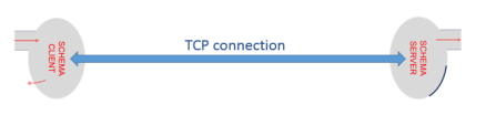
Each side of the tunnel connection can support any number of schema clients and servers, so the tunnel can connect two arbitrary sets of Ubisense processes over any network that supports TCP.
Partitioning
The Ubisense architecture supports many ways of partitioning services in order to increase the options for scalability. In general, it is possible to run multiple copies of the same service in order to provide load balancing. This can be achieved very simply in some cases where services just consume data for delivery to other systems (e.g. a service which displays maps over the web may have many copies according to user requirements). But when services actually store and publish data, some kind of data partitioning scheme is required. The most important partitioning scheme in SmartSpace is cellular partitioning.
Cellular Partitioning
SmartSpace manages location data using a cellular architecture. This ensures that:
- systems can scale to cover large physical areas by splitting the areas up into cells, and
- real-time data for nearby objects is generally handled by the same schema instance
The cellular decomposition is generally into a hierarchy with three levels as shown in this diagram. Each of the levels has its own special role.
![]()
The cells are used to create a kind of schema federation: a service can run at the level of a Site, geometry cell, or location cell, and in the case of geometry and location cells multiple copies of the service will be run. This diagram shows an example with services organized according to the hierarchy above, showing just the ‘location management’ services; each location cell level schema has a copy running for each location cell, each geometry cell level schema has a copy running for each geometry cell, and each site level schema has one copy:
![]()
Location Cells
Location cell level is where location data (e.g. (x,y,z), rotation, …) is managed, by location cell manager schemas. One location cell manager schema runs for each location cell. The data in a location cell manager is usually directly input from sensor systems, or set manually by a remote operations interface. In a vehicle production plant a location cell might cover (e.g.) one or more individual bands of a production line, the space between two production lines, part of a logistics area.
The aggregate event rate across all the location cells is generally equal to the total event rate produced by all location sensor systems being used. As the location sensor systems become more capable, and generate higher event rates, the event rate at location cell level will increase.
Geometry Cells
Geometry cell level is where relationships between objects are evaluated. The key component of this is the spatial monitor schema. One spatial monitor schema runs for each geometry cell. The spatial monitor process consumes data from all the location cells underneath it, together with data from the spatial ownership schema, and publishes a new schema that contains the set of all interactions between objects within its cell.
A very important property of the geometry cell is that the aggregate event rate of interaction data is essentially independent of the event rate at the underlying location cells. For example, a tool tracked at 10Hz generates 10 location events per second, but if it is placed inside a vehicle it generates one interaction event (when the interaction is asserted), and then no other events until it is removed again (when the interaction is retracted). Thus geometry cells isolate applications from the high data traffic generated by sensor systems.
Site Cell
There is normally a single Site cell, where data is managed if it does not have a significant real-time component. For example, this includes site layout and appearance, most properties of objects, details of the spatial properties of objects and so on.
Cellular Applications
An important feature of SmartSpace is that application logic itself should execute at an appropriate level in order to avoid creating bottlenecks in applications. For example, application logic that processes (x,y,z) location data will execute at location cell level to ensure that it scales correctly as the system size increases.
Aggregation
Sometimes it is desirable to have an overview of all data at Site level, but this needs to be done without concentrating a massive event rate at a single service. To achieve this we use aggregated services. An aggregated service has copies (i.e. processes containing schema servers with the same signature) that run at all the cells above some specified level. An aggregation client running at some level will consume data from the schema at its level and throttle the event rate so that it changes the state at the schema in the parent cell with some configurable rate limit. In this way the top level cell will manage data that aggregates the data below it but maintains a configurable upper limit on the event rate.
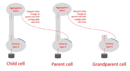
One of the most important aggregated services in SmartSpace is the location aggregation service, which generates a Site level view of location data with a guaranteed rate limit. The diagram below shows the location aggregator services running in the configuration defined previously.

Processing
Processing Nodes
A processing node is a computer with networking and (optionally) non-volatile store. A Ubisense system can contain one or many processing nodes.
One processing node is chosen to host the Ubisense core services. These are a small set of basic schema services that are necessary to describe the structure of the system and manage its fundamental configuration data. All other services may be deployed to any processing node. Processing nodes can be added or removed at runtime and services may be freely migrated between them.
Processing nodes may run Linux (basically any post-2.6 kernel) or Windows (basically any post-XP OS version). The same system may contain both Linux and Windows processing nodes freely mixed.
Ubisense Service Administration Schema
The service administration schema is a Ubisense schema that manages all the data relevant to schemas, their level in the cell hierarchy, their assignment to processing nodes, and their status.
Mapping cells and services to nodes
Normally it makes sense to nominate a processing node that a group of services would be expected to run on, perhaps because the services in some group communicate heavily with each other and would run more efficiently on the same machine. In the service administration schema, nodes can be assigned to services individually, or nodes can be assigned to a cell, and indirectly to all the copies of services running within that cell.
Ubisense file server
The service administration schema works together with a file server that stores relevant files (e.g. service executables, data files, and resources like COLLADA models or SVG images).
Managing service status
The service administration schema allows the user to specify the desired status of a service or services at a given cell or cells. Example status values might be: running on node N; stopped on node N; not assigned to any node. The schema also records the actual status of each service/cell pair. Service administration then ensures that the actual status is changed so that it matches the desired status.
Local controllers
The operations necessary for service administration are performed by a special service called the local controller, a copy of which runs on each processing node. The local controller contains a service administration schema client, and its job is to download, start, stop, or upload executables and data files to ensure that the actual state matches the desired state.
For example, if the location cell server at Cell 1 is assigned to node N1, and it is reassigned to node N2, the controllers on the respective cells do the following:
- N1: stop the process for the location cell server at Cell 1
- N1: set actual status of location cell server at Cell 1 to stopped
- N1: write back any modified data files to the file server
- N1: set actual status of location cell server at Cell 1 to not assigned to any node
- N2: set actual status of location cell server at Cell 1 to assigned to N2
- N2: read required executable and data files from the file server
- N2: start the process for the location cell server at Cell 1
- N2: set actual status of location cell server at Cell 1 to running on N2
Third-party Service Administration
Ubisense service administration is especially convenient for managing SmartSpace, because it is aware of the fundamental concepts of cells and services. But it is also possible to run a Ubisense system using some third-party management software if this is desired, replacing the Ubisense administration methods and not using the local controllers.
Elasticity
In some cases it is desirable to have a mixture of Ubisense service administration and third party administration systems. A good example of this is in managing visibility applications in some environment with a large user population, which is handled very well by running some SmartSpace services within an existing elastic computing framework, and simultaneously running real-time control systems using high-bandwidth sensor systems, which is handled best by running other SmartSpace services within the standard Ubisense service administration framework.
Working with standard elastic computing services
The SmartSpace web map is composed of three main components: a query service that uses multiple caching schema clients (including the user data schema, the aggregated location schema, and search configuration schema) and performs queries over user data, returning results to a web service hosted by a web server that deals with http invocations directly to update a web client that manages the user interactions, executing queries and displays the results on a map.
In the default distribution, a single copy of the query service is configured to be run by the service administration support at site level. But it is simple to reconfigure the service administration schema so that the query service is not directly managed by Ubisense, and instead to package all three web map services within an elastic computing environment. Using standard techniques, multiple copies of the three services can be executed by the elastic computing environment, according to demand.
Because the query service retrieves its data using the Ubisense event channel protocol, which is 1:N and asynchronous, and stores data in a local cache, extra copies of the web service can be created without adding any additional synchronization overhead to the SmartSpace platform. Therefore, with sufficient processing resources, the package of services can be made to scale to an essentially unlimited user population.
Repartitioning the cell hierarchy
Standard commercially available techniques for dealing with scale do not work so well when we need to sink data at high update rates from sensor systems, while detecting interactions between arbitrary pairs of objects. In order for a computing system to detect an interaction between two data items, those items must both be present in the same process address space at some point, therefore standard partitioning techniques will not work because they rely on random assignment to processing units. This is why the SmartSpace platform supports cells as a basic concept.
If the aggregate data rate at an individual cell becomes excessive then using SmartSpace it is possible to reconfigure the cell hierarchy on the fly e.g. to split a location cell into two, or to add extra geometry cells. When this is done, service administration ensures that the relevant SmartSpace schemas are automatically deployed to appropriate nodes and started with the relevant data, and client schemas rebind dynamically to the new processes.
Important SmartSpace services and their role
Core Services
The core services are a small set of services that are required in order to run any Ubisense system. They include: the inheritance database, which stores the Ubisense multiple inheritance type hierarchy; the cell configuration schema, which stores the cell hierarchy; the service administration schema, as discussed in the previous section; the permissions schema, which stores the role based schema security configuration; the multicast assignment schema, which stores assignment of multicast channels (if multicast is used) to schemas; the global configuration schema, which stores configuration parameters relevant to every Ubisense service (for example, configuration of the basic protocols); and the file server, which is used in the service administration process.
The core services typically have a very low event rate, and their schemas store a fairly small amount of data.
Location Cell Manager
The location cell manager stores and publishes location data. It runs at location cell level. It includes various techniques for handling high update rate streams (e.g. from tagged objects), which also managing storing data reliably (e.g. the positions of stationary objects placed manually during configuration).
Spatial Monitor
The spatial monitor translates location data into spatial relationships. It runs at geometry cell level. The spatial monitor is a fundamentally important service that translates raw location data into spatial relationships that are relevant to applications and simultaneously isolates applications from the high data traffic generated by sensor systems.
Location Constraints Services
Location constraints services use real-world context information together with tag data to derive more accurate location for the objects driven by tags. For example:
- Using data about paths and queues to constrain object positions. For example, on a vehicle production line cars move along a fixed line at a near constant velocity, frequently with fixed distances between the car tags. This information can be used to constrain car positions to a much more accurate result than the underlying tag data.
- Using data about parking spaces to constrain object positions. For example, in a yard, vehicles are parked in certain parking bays with a given orientation. This information can be used to help determine which bay a car is parked in and to fix the orientation of the car.
These services are all schema clients running at location cell level, normally caching the relevant location cell data and modifying it using the remote operations interface, or occasionally running in the same process as the location cell manager itself.
User Data Store and Rules Engine
The user data store manages arbitrary user-configured properties of objects. For example, some piece of tooling equipment might have a count for the number of times it has been used, a date for when it was last recalibrated, and thresholds for the required frequency of recalibration expressed as a combination of time interval and number of uses since the last calibration. All this data can be defined as user-defined properties and stored in the user data store.
In addition the user data store contains a rules engine. Using the rules engine it is possible to express logical relationships between properties of user data. For example, the conditions under which a tool needs recalibration can be expressed using the rules engine; this data would then be available to alert maintenance staff and direct them to the location of the tool on a map.
Assertion Store
The user data store is primarily for supporting visibility applications that require an overview of a site (or multiple sites). The assertion store is a store of application-level facts that are more geared towards real-time control applications; for example, while the user data store might deal with data about a tool’s calibration status, the assertion store might deal with facts like ‘the tool is next to product X in workspace Y’. The assertion store runs at geometry cell level and at site level and is also partitioned into separate schemas depending on activity, to provide multiple low latency event channels for control applications.
Search Client Interface
The search client interface implements the query service described in the section above about elastic services. It has a schema client cache of the user data store and provides configurable searches and display styles for use by people taking various operational roles in the site.
SmartSpace platform operational use cases
Remote Access
The protocol tunnelling capability is packaged into an application called Site connector. This can be run as a service (e.g. to connect two separate sites together across the public internet), or as an application (e.g. on a laptop running a set of Ubisense administration tools, to perform remote administration).
It is common practice to manage large production Ubisense software installations remotely via Site connector.
Installation
Services are shipped in packages that contain an XML description file plus one or more of: executables, libraries, resources and data files. Services are installed by using the service installer, which caches the service administration schema and is also a client of the file server. The service installer reads the description file and updates the service administration schema to register the new services and uploads the required files to the file server.
Service installation is done entirely using Ubisense protocols so it can be done from any machine in the Ubisense network, or remotely via the Site connector application.
Upgrade
The service administration schema includes version information, so service upgrade is just a question of installing the appropriate new service version using the service installer.
Because of the dynamic binding properties of the Ubisense architecture, upgrade of individual components can be performed while all other components are running. Any necessary rebinding is accomplished automatically.
Simple Backup
The service administration schema provides support for a simple, stop-and-copy backup. If this is selected a service/cell pair, the relevant local controller stops the corresponding process, copies its data files back to the central file server, and restarts the process. This ensures that the central server contains a copy of correct data for that service/cell pair at the time of the backup.
Replication and Hot Backup
All Ubisense schemas support a replication option that acts at the level of the commit logs in the schema persistent store; every commit log write is duplicated with another write to a replication queue; the replication queues are consumed by a replication daemon that writes over TCP to a remote client, which reconstructs the schema data files on a remote store. This mechanism is used to support asynchronous replication of all the schemas on a given processing node, and is a convenient way of implementing a hot backup in software.
It is also possible to achieve replication by using a SAN attached to one or more processing nodes, and using hardware replication support at the level of the SAN.
Failover
The service administration schema contains the complete specification of the system state, referring to processing nodes by name. The local controller service that runs on each processing node includes the option to specify a node name at run time, so it is possible to implement a failover mechanism by using any supporting replication method together with a set of scripts that run up local controllers with a suitable name specification.
Shadow Systems
In order to support operation of shadow test servers, Ubisense schemas also support a ‘property transfer’ mechanism that supports injection of selected data changes from a source to a target Ubisense installation. This can be used to take data from a production system and inject it directly into a test system, to provide realistic regression and new feature test support.
SmartSpace Visibility
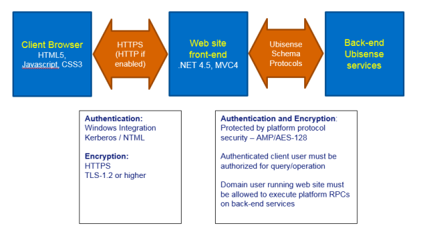
The SmartSpaceVisibility component differs from the other components in that it provides various user interface via a web server, and therefore uses standard web protocols as well as the protocols used by the rest of the SmartSpace schema services. This section describes the web site structure, how it interoperates with the rest of the Ubisense system, and the relevant security considerations.
Basic Structure of the Web Site
The web site is separated into front-end and back-end. The front end is concerned with authentication and the serving of web site pages, JavaScript code, style sheets and image resources to the web server clients. The back end is concerned with processing application logic, such as search execution, updating platform state based on front-end requests, and integrating with other components of the SmartSpace platform.
Web Site Front-end
Implementation
The web site front-end is implemented using Microsoft MVC4.0 hosted in an IIS web site. The web site will use the configured IIS ports, which should typically be 443 for https, and port 80 if http is also allowed.
The web site folder structure is split into MVC areas, where each area implements a single tab in the web site front page, for example “Maps” or “Reports”. For example, all content web pages for the Maps area is under the relative URL SmartSpace/IF. This corresponds to the folder <webroot>/Areas/IdentifyFind/.
Browser code is entirely HTML5/CSS3/JavaScript. The content of the pages is dynamically build using queries back to the front-end via GET and POST verbs. When the user changes application state, such as acknowledging an alert or setting an object property, these are also implemented via GET verbs back to the front-end. These query and operation requests are served from separate URLs within each area, so for example the queries for the Map are served from the relative URL SmartSpace/IFAPI. These queries are authenticated by IIS, and then passed directly from the front-end to the back-end services for execution, along with the authenticated user and the locale of their browser for translation purposes.
Query data is encoded using JSON, and the JavaScript code maintains a strong separation of content from code. For example, query results are always escaped before insertion into HTML as text, to prevent HTML or JavaScript code injection based on data. One exception is that specific formats of HTML links (<a>…</a>) are allowed in presented data, but only with a very limited format to avoid injection.
Communication between front-end and back-end is via normal Ubisense platform RPCs.
Security
Since the web site uses .NET for its server side code, it is important that security updates to .NET should be regularly applied. Since this is a widely used dynamic web site technology, these are high priority within Microsoft.
For a secure installation, best practice for hardening IIS should be followed, for example:
- configuration to use HTTPS only, using the latest protocols (e.g. TLS-1.2 or higher)
- ensure that detailed error pages are not visible to external users
- limit the maximum size of requests handled
- filter requests by source domain name if possible
Authentication is implemented via Windows integrated authentication. If NTLM v1 is enabled for the server and domain, this will be available to the IIS server front-end. However from SmartSpace 3.7, NTLM has been disabled as an authentication provider in the web site installer. If it is needed, it can be added manually using IIS Manager, after careful consideration of the security concerns in using NTLM. Instead, IIS can be configured to require Kerberos authentication and this is recommended, since NTML v1 has a number of vulnerabilities.
Communication between front-end and back-end can be secured in the normal manner using the platform Security Manager. In particular, if the IIS application pool for SmartSpace Web is configured to run as a domain user, the platform protocol can also be configured to secure the relevant schemas for access by that domain user (the detailed instructions are included with the Visibility component software).
Web Site Back-end
Implementation
The back-end uses the Ubisense platform protocol to communicate with the front-end. The back-end runs as normal Ubisense services which are deployed and controlled through the Ubisense service manager. They need not be running on the same server as the IIS web site.
Security
See the separate discussion of Ubisense protocol security for a description of how the protocols are secured.
The back-end implementations of queries and operations first check that the authenticated user passed from the front-end (with integrity protected by the platform protocol security) has a role which is authorized to perform the query or operation. If LDAP has been configured for the SmartSpace platform, the users and roles can be LDAP users and roles, to allow central maintenance of authorization.
The only back-end scripting facilities are in the SQL interfaces (Applications integration component and Reporting component).
The Visibility component has no scripting, so code injection in the back-end is not a direct concern. For SQL interfaces, all JSON data is always either escaped before execution, or is presented as binary parameters to the SQL instance, so it cannot be misinterpreted as code.
SmartSpace platform scalability use cases
Aggregate Event Rates and Latency
Key scalability features: By using the inbuilt support for cellular partitioning it is possible to divide up a space into cells, and run copies of the application logic at each cell. Each process has its own asynchronously-updated cache of the data that it uses, so there is no contention or synchronization overhead across cells. Processes can be assigned to the same machine or to separate machines in an arbitrarily-large cluster.
We have deployed real-time control systems using a single machine (8 Xeon 4-core), with an aggregate location event rate of ~3500Hz, simultaneously detecting interactions between 1000 vehicles, 250 tools and 100 handheld devices and applying simple location rules to send messages to remote devices with latency <100ms.
In this case cell partitioning is 17 location cells, 9 geometry cells, with a total of about 80 processes handling control system data. This machine is also running the RTLS system management services. We estimate that by adding processing alone (extra machines in a cluster) and deploying services across the processing, aggregate event rate could be raised to approaching 105Hz with no increase in latency.
Large Numbers of Objects
Key scalability features: Object memory footprint is small (7 x 32bit words per object reference). Type and format descriptors are stored separate from data to ensure that storage space is limited to the data itself.
For storage of objects without significant application-level behavior (e.g. logistics applications) about 105 objects for an individual type is a reasonable figure. For objects with complex near-real-time behavior (e.g. product going through a complex process of production, rework, test and yard storage), our Offline application is designed to deal with over 10,000 vehicles across a single site, keeping track in real time of process state, timeouts and alerts.
Large Numbers of Users
Key scalability features: As described in the earlier section on Elasticity, schema client processes that use data from multiple schema servers can be copied. Because the Ubisense schema clients receive data using the Ubisense event channel protocol, which is 1:N and asynchronous, and store it in a local cache, increasing the number of client processes does not add any synchronization overhead to the producer services.
It is therefore possible to support large numbers of thick client applications on a Ubisense system because the individual client processes do not themselves add any overhead on the server side.
SmartSpace multi-site operation use cases
The SmartSpace platform is normally intended to be deployed at individual sites, but it has also been used to support multi-site operations. This section outlines the different options and use cases.
Single System, Multiple Sites
For example, to support distributed production of airliners, we have deployed the Ubisense software across six separate factories across Europe. In this case we used a single central processing node and separate individual processing nodes at each factory, connected to the central node via the site connector protocol tunnel. The relevant location and geometry cells were migrated to the individual factories, with the site level services running at the central server. Because services in separate cells are isolated, there is no need to support communications between individual factories.
Multiple Systems, Application Integration
Another approach to multi-site operation is to run multiple systems and integrate at the level of application data. In general, real-time control applications are only relevant to the local site, so the value of multi-site operation is in the area of visibility. It is likely that SmartSpace can support the relevant visibility use cases by using its support for hyperlinking: for example, suppose a product is assembled at a certain site and it has components assembled at another site, it is possible to view two different maps simultaneously by simply hyperlinking to the relevant objects specified by name.