Paths and queues configuration
What is Paths and queues?
Paths and queues is a feature introduced into the Location Rules component of SmartSpace 3.4. Its purpose is to allow you to introduce prior knowledge of object locations in your system, in particular when objects travel along fixed paths like this:
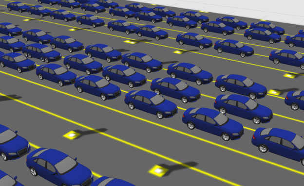
When you configure Paths and queues to control objects, they will be snapped to nearby paths as tags move around. You can introduce further constraints to control object speed and separation such that objects form queues along the paths. You can then use the object sequence information in your application to report things like “number of vehicles in front”.
Paths
Paths are physical routes that you know objects will follow. You draw these in SmartSpace Config:

Paths configured to keep object neatly positioned within the lanes
Path constraints
Path constraints are normally intended to match the real-world, physical, immutable constraints of the thing being modeled. In SmartSpace 3.4, the following constraints are configurable:
- Rotates – object rotations, which can change as they move along a path
- HasSpeed – object speeds
- IsInTrain – object separations
For example, a production line might move at a known constant speed that won’t change over time. In this case, you could use the HasSpeed constraint.
Path sections
Paths can be split into sections in order to assign different constraints to different sections of the path.
Path points
A path point is an object intended to be located exactly on a path. There is an object type called Path Point that you can use directly, or inherit, to give objects special UI features to get them to snap to paths or generate them at regular intervals.
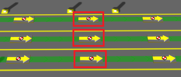
Path points, automatically generated at regular intervals
Path groups
A path group is a logical grouping of paths used to determine which objects are being controlled by the path tracking location rules. A path group has an extent which, by default, is used to determine which objects to control.
How do I get Paths and queues?
Version and license
You will need SmartSpace 3.4 with a license for Location rules.
Installation
Click Install services... in Service Manager to install service packages. If you have a license, Paths and queues will appear in the list of features:
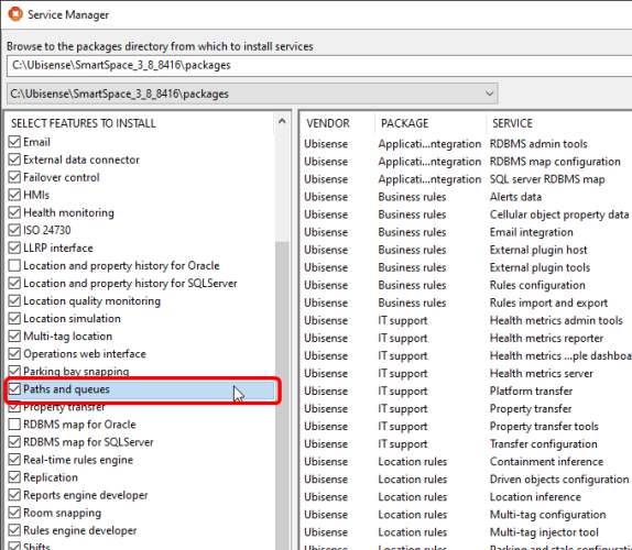
Selecting the Paths and queues feature in Service Manager
Where does Paths and queues appear?
Once you have installed Paths and queues, since it is integrated into existing SmartSpace components, it will appear in various places in Ubisense programs.
Service Manager
In Service Manager, there are some new Location rules services:

Service Manager showing Paths and queues services
Application Manager
In DOWNLOADABLES, there are new items in the Location rules task:
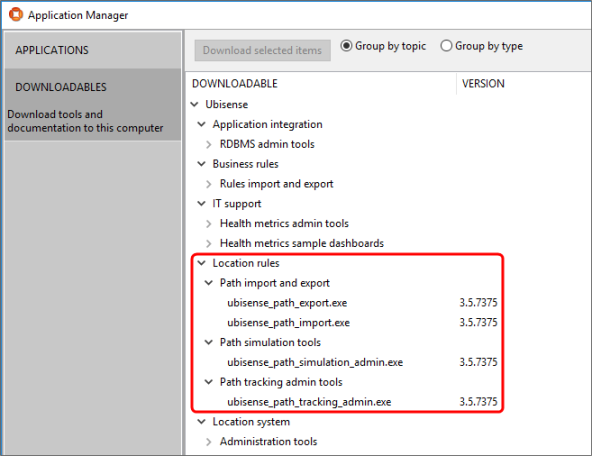
Application Manager showing Paths and queues downloadables
SmartSpace Config
In TYPES / OBJECTS, there are two new types:
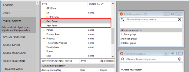
SmartSpace Config TYPES / OBJECTS automatically has two new types
There is a new task called PATHS:
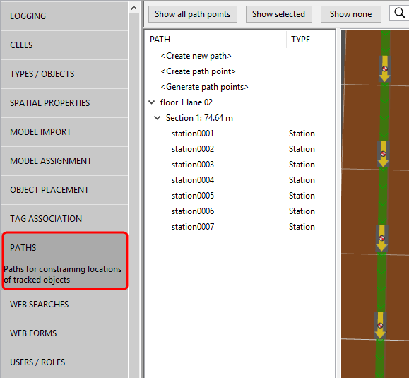
SmartSpace Config PATHS task
In SERVICE PARAMETERS, there are new options in the drop-down list:
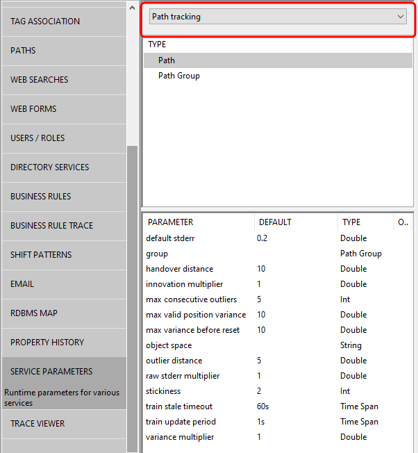
SmartSpace Config path tracking service parameters
Creating the data model for Paths and queues
Using the PATHS task
Use the PATHS task in SmartSpace Config to model the physical layout and constraints of your environment.
Draw a path

Getting started in SmartSpace Config PATHS
When drawing a path, read the instructions carefully to ensure you know all the capabilities of the tool. You can line paths up neatly using the Snap grid and Path height controls.
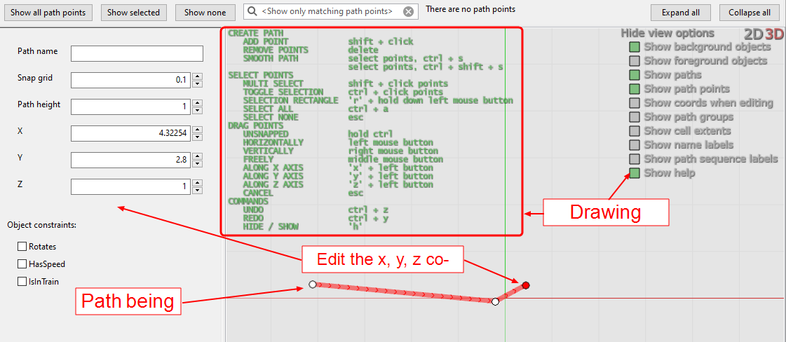
Drawing a path in SmartSpace Config PATHS
See the green drawing instructions on the map for how to smooth a path to look like this:

Drawing a smoothed path in SmartSpace Config PATHS
The path will always go through the control points, so if the smoothing doesn’t behave as required, add more control points.
Add path constraints
If your environment has physically constrained paths, use the path editor to add constraints:
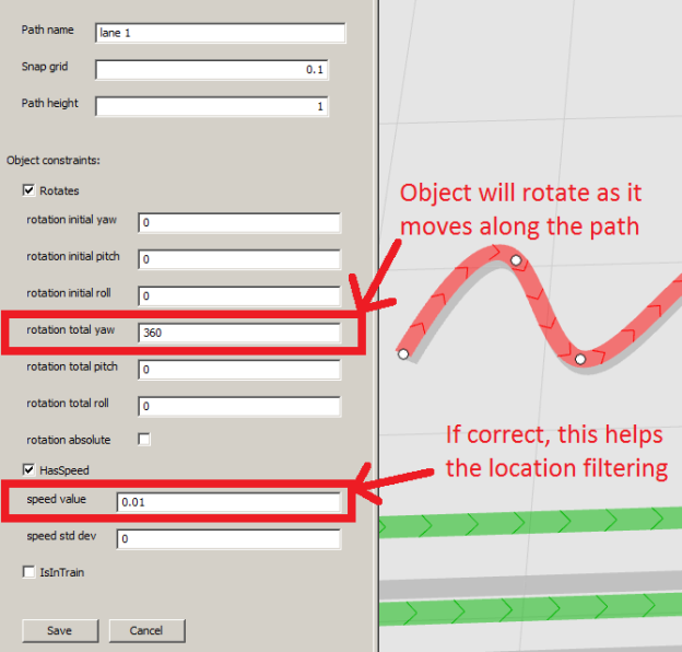
Adding path constraints in SmartSpace Config PATHS
If your path has different constraints in different sections, you can split the path by following the instructions in the in-place help in the PATHS map.
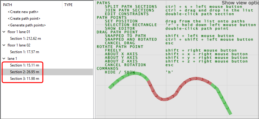
A path split into three sections in SmartSpace Config PATHS
Double-click individual path sections to edit constraints separately.
Generate path points
Use <Generate path points> to automatically generate objects at regular intervals along paths. You can create types that inherit from Path Point in TYPES / OBJECTS. To avoid confusion, give them a representation using MODEL IMPORT and MODEL ASSIGNMENT before creating any.
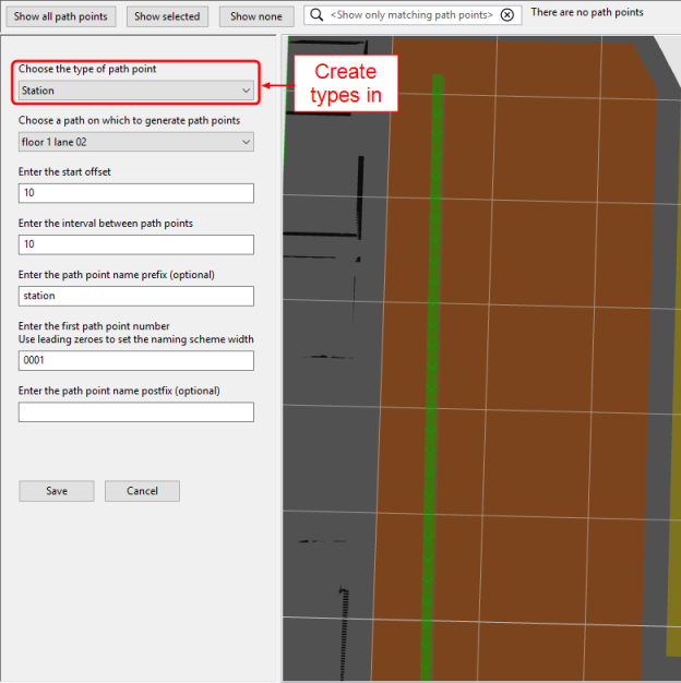
Generating path points in SmartSpace Config PATHS
There is nothing special about objects created in this way, other than the fact that their name and location were generated by SmartSpace Config. You can see them in TYPES / OBJECTS, give them properties, and use them in SmartSpace Business rules if you have the appropriate licenses.
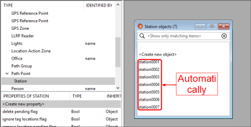
Path points are normal objects in SmartSpace Config TYPES / OBJECTS
2D Reps and Path Points
When creating path points, the path point generation code places the path point object instances at exactly the same position on the z axis as their path. If the path point type has a 2D rep with a z offset of zero, then the point is exactly coplanar with the path section ribbon and this might lead to you seeing rendering artifacts.
It can also make it difficult to select a path point: sometimes clicking the point might pick it, or it might pick the path section instead.
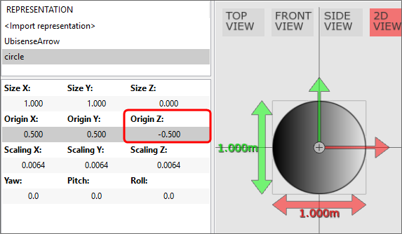
To make path points easier to select, you can set a non-zero z origin offset (e.g. -0.5) on the representation used for Path Point (the base type used when generating path points). Any path point types you create will inherit this rep and its default offset.
For example, if you decide to use a rep called circle, a simple 2D circle, for your path points, when you import the image in MODEL IMPORT, in addition to any scaling you apply, also set the z origin:
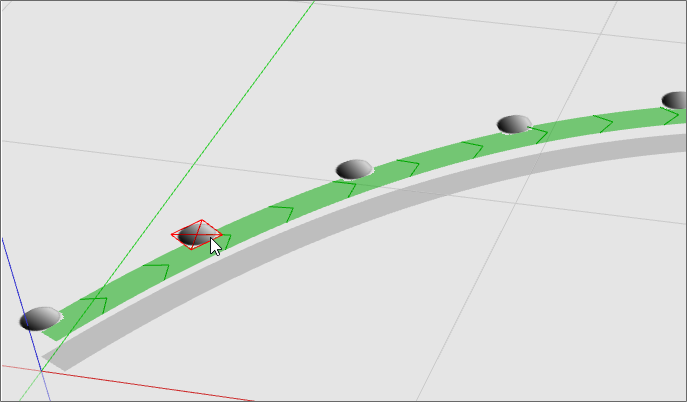
Assign this rep to the Path Point type in MODEL ASSIGNMENT and then any path points generated using this rep, will "float" above the path:
Moving path points
Since they are normal objects, you can drag path points around in OBJECT PLACEMENT. However, this doesn’t snap them to paths. The PATHS map will warn you when path points are not on a path:
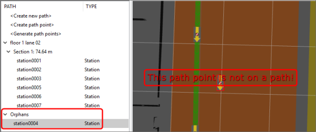
SmartSpace Config PATHS map warns about orphaned path points
Fix this error by double-clicking on the path point to bring up the editor:
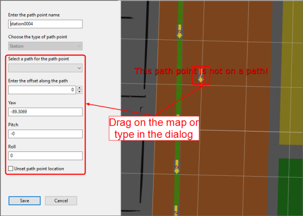
Moving a path point using the editor in SmartSpace Config PATHS
Controlling path tracking
Path-to-group mapping
You must assign paths to groups using SERVICE PARAMETERS. Select Path tracking and Path in the dropdowns. Drag the group parameter onto the right-hand panel. Assign path groups as required.
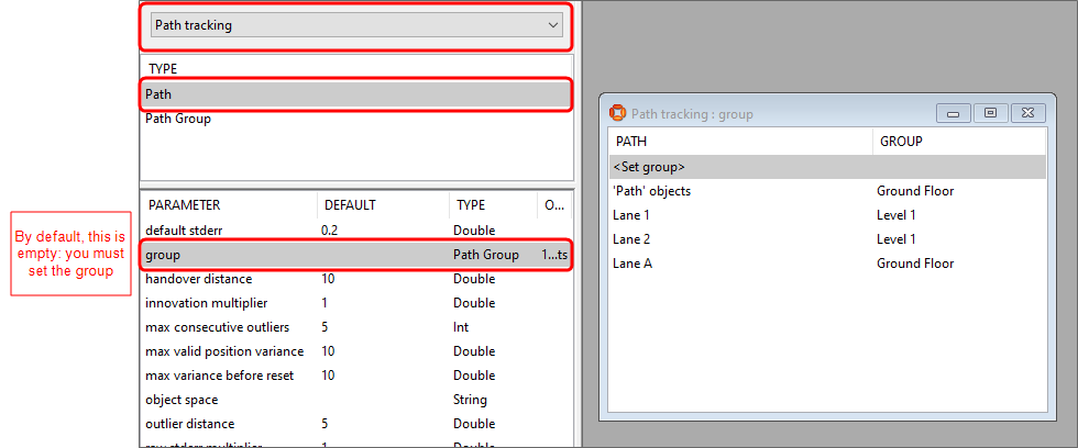
Assigning paths to groups in SmartSpace Config SERVICE PARAMETERS
Default containment
The default path tracking behavior is to control objects that are contained in the extent of a path group. To set this up, create objects of type Path group in TYPES / OBJECTS. Set their extent property in SPATIAL PROPERTIES:
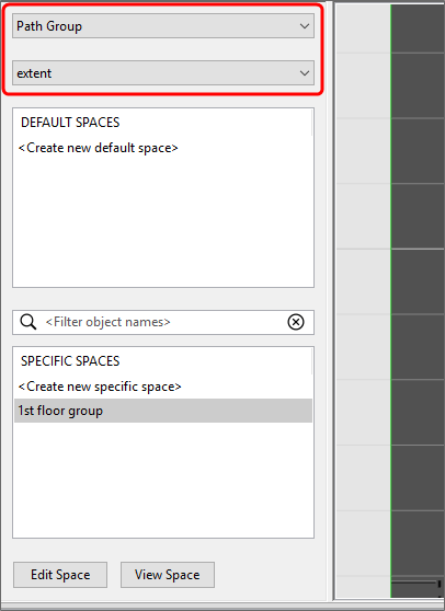
Creating path group extents in SmartSpace Config SPATIAL PROPERTIES
Create a SPACE property for the objects to be controlled in TYPES / OBJECTS and SPATIAL PROPERTIES and monitor the spatial relation:

Setting up default containment in SmartSpace Config SPATIAL PROPERTIES
Controlling objects using business rules
For some applications, you might need to decide which objects are controlled by path tracking based on some other business logic. For this, you will need SmartSpace Business rules licenses.
First, turn off default containment in SERVICE PARAMETERS:
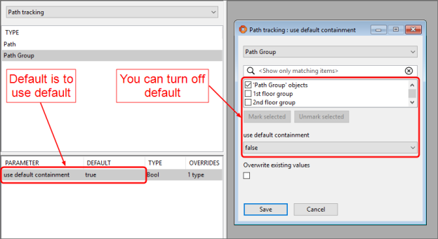
Turning off default containment in SmartSpace Config SERVICE PARAMETERS
Then, use BUSINESS RULES to set and unset rows for <Path Group> controls <Object> as required:

Setting <Path Group> controls <Object> using SmartSpace Config BUSINESS RULES
Advanced path tracking parameters
Path tracking uses filtering to estimate the offsets of objects along paths. You might need to change filter parameters for some or all paths in your model, depending on the layout, quality of the location system, and so on. For example, if you have lots of lanes alongside each other, you might need to make them “stickier” such that objects change lane less readily.
Always test your application with the default values before changing anything described in this section.
In this context, “variance” means how uncertain the filter for a particular path is that it has the object in the right place.
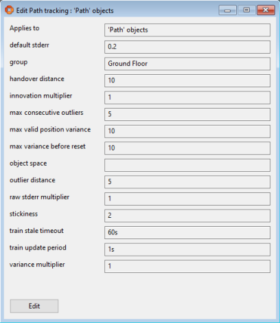
Using SmartSpace Config SERVICE PARAMETERS to change path tracking filter parameters
default stderr
The value to use when the sensor system fails to provide an estimate of the measurement accuracy.
Do not normally change this parameter.
handover distance
When the filter resets, the path position is chosen to minimize the distance between the expected and the actual tag location. When resetting the filter, this parameter is the distance above which path tracking will allow other location rules to be applied.
-
higher = path tracking will hold onto objects more, possibly without generating locations
-
lower = path tracking will allow other location rules to take over more easily
Set this higher if tags are coming off paths too easily.
Set this lower if tags are getting stuck on paths when you want other location rules to take over.
innovation multiplier
Multiplier applied to the inferred error based on the distance from the estimated tag position to the measurement. For example, if this is zero, the distance from the estimated tag position to the measurement will not directly affect the filter variance at all.
- higher = measurements further from the estimated tag position will be trusted less
- lower = distance from estimated tag position to measurement doesn’t matter as much
Set this higher if tag locations that are far away from the estimated tag position are placing the object on the path incorrectly.
max consecutive outliers
The maximum number of consecutive measurements deemed to be outliers before the filter resets to the nearest point on the path to the next measurement.
- higher = filter will reset less readily; objects will make fewer big jumps
- lower = objects will jump to the nearest point to the measurement more easily
max valid position variance
The maximum value of the filter variance for which an object location will be generated.
- higher = generate more locations, potentially of lower quality
- lower = generate fewer locations, but with more certainty that they are correct
Set this lower if your application requires locations to be generated with more certainty.
Note that it doesn’t make sense for this to be larger than max variance before reset; the filter variance will never be higher than that (because it will reset instead).
Note that it doesn’t make sense for this to be larger than
max variance before reset
The maximum possible variance of the filter state. When the variance goes over this value, the filter resets to the nearest point on the path to the next measurement.
- higher = filter will reset less readily; objects will make fewer big jumps
- lower = objects will jump to the nearest point to the measurement more easily
object space
The spatial property used to determine if adjacent objects' spaces intersect and hence attempt to prevent objects overlapping.
Use the object space parameter when you want to prevent the overlapping of objects, you have your paths lined up such that there is likely to be a good alternative path for an overlapping object, and the 'IsInTrain' constraint is not suitable. To use it, you need a spatial property which has relative spaces defined. You then set the spatial property in object space to this property name, ensuring the string matches exactly the name of the property as it appears in SmartSpace Config. For example, for a type T with spatial property ‘extent’, you can use “extent”, “extent of ‘T’” or “the extent of ‘T’".
In use, when you get a tag location update, if the new object position is such that the object space intersects the space of an adjacent object on the path, it will look for an alternative path to prevent overlapping. If there is no alternative available, the object is located on the best path as usual.
Note: Using the object space parameter doesn't guarantee that objects will never overlap. It also does not create a train of objects: use the 'IsInTrain' path constraint if that behavior is required.
outlier distance
The minimum distance between the estimated tag position and the measurement where the reading is defined as an outlier. See max consecutive outliers for a description of what outliers do.
- higher = filter will reset less readily; objects will make fewer big jumps
- lower = objects will jump to the nearest point to the measurement more easily
Set this higher if your readings are very noisy and you want to stop objects making a lot of jumps.
raw stderr multiplier
Multiplier applied to the raw error computed by the sensor system. For example, if this is zero, sensor measurements will be assumed to be completely correct by the filter.
- higher = noisy measurements from the sensor system will be trusted less
- lower = sensor system noise doesn’t matter as much
Set this higher if noisy sensor measurements are placing the object on the path incorrectly.
stickiness
Number of consecutive tag measurements for which a path filter needs the lowest variance in order to take control of the object.
- higher = path will hold onto objects; objects will flicker between paths less
- lower = path will release objects to other paths in the same group more easily
Set this higher if objects jump back and forth incorrectly between paths.
train stale timeout
Objects on a path section with the IsInTrain constraint are all moved at the same time. The train stale timeout is the period after which an object is no longer moved with the train when its tag has not been seen. For example, a tag might be disassociated without retracting the path group controls object assertion, in which case it will stop moving with the train once the timeout is reached.
-
higher = an object with no tag or whose tag has not been seen will continue to move with the train for a longer time
-
lower = an object with no tag or whose tag has not been seen will be removed from the train more promptly
-
zero = the timeout is disabled such that objects will continue to move in a train until 'path group controls object' becomes false or the relevant 'Location inference' service is restarted
Normally, you should use the default value of 60 seconds and avoid relying on the timeout by ensuring all objects have a tag that can be seen by the location system, then retracting the path group controls object assertion (using the path group extent or a business rule) whenever a tag is removed.
train update period
Objects on a path section with the IsInTrain constraint are all moved at the same time, at a rate defined by the train update period (default = 1 s), so by default a train moves at a maximum of 1 Hz. Note that the parameter is a time span, which is the reciprocal of the rate.
-
higher = object trains will move less frequently and generate fewer location events
-
lower = object trains will move more frequently and generate more location events
Set this higher if there are more location events than can be handled by the system.
Set this lower if the locations of objects in trains are not staying up-to-date.
variance multiplier
Multiplier applied to the variance prediction as time elapses. When the filter predicts a new state, the variance increases because time has elapsed since the last measurement. The elapsed time is multiplied by this value when increasing the variance over time.
- higher = filter will be quicker to reset or handover to other paths or location rules
- lower = filter will take longer to reset or handover to other paths or location rules
Paths and queues simulation
What is the simulator?
The SmartSpace Location rules component includes some support for simulating tags or objects moving along paths. This is a good way to ensure you have set everything up before deploying Paths and queues into production.
From version 3.6, the Location simulation feature provides a more sophisticated method of simulating object movements in SmartSpace using business rules.
Services
Path simulation services are included in the service packages for the SmartSpace Paths and queues feature:

Path simulation services shown in Service Manager MANAGE SERVICES
The Path simulator services wait for a simulation request, so you can leave all these services running all the time. Simulation only starts when you use the admin program to request a simulation.
Admin tool
You can download the simulation admin tool using Application Manager DOWNLOADABLES:
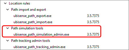
Path simulation admin tool shown in Application Manager DOWNLOADABLES
Use the admin tool to set the service parameters used by the simulator.
Simulator service parameters
In SmartSpace Config, SERVICE PARAMETERS shows the parameters that are set by the admin tool and consumed by the simulator services:
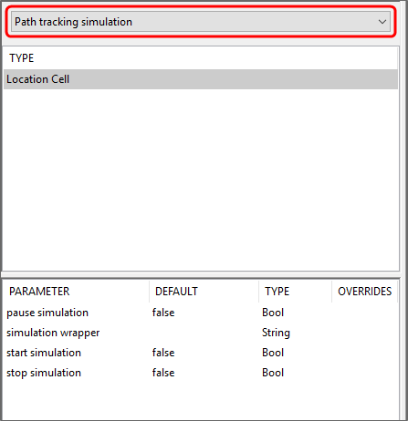
Path tracking simulation in SmartSpace Config SERVICE PARAMETERS
Example simulation walkthrough
Create the XML script
To create a simulation script, start by running this command:
ubisense_path_simulation_admin.exe example > path_simulation.xml
Edit path_simulation.xml to see the format and example data. The following steps will make it work without modification.
Create objects to attach to simulated tags
In SmartSpace Config TYPES / OBJECTS, create 20 objects of type “Car”:
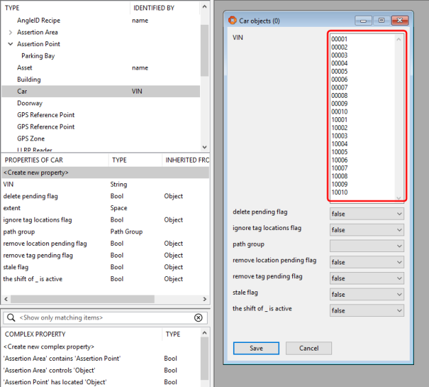
Make sure “Car” has an assigned representation model by using MODEL IMPORT and MODEL ASSIGNMENT.
Attach tags to the objects
Use TAG ASSOCIATION to attach tags. The IDs need to match those that will be simulated in the XML script:
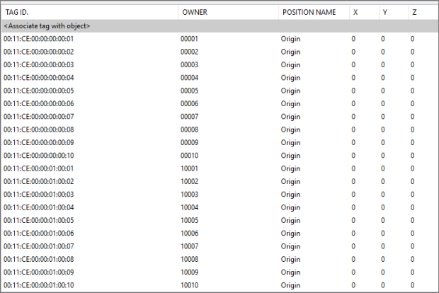
Simulated tags assigned to cars in SmartSpace Config TAG ASSOCIATION
Create paths
Use TYPES / OBJECTS to create a Path group.
Use PATHS to create “path1”, “path2”, “path3” and “path4”:
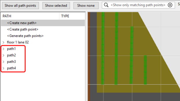
Creating paths for simulation in SmartSpace Config PATHS
Assign a path group
Assign the paths to a group in SERVICE PARAMETERS:
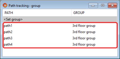
Assigning path groups in SmartSpace Config SERVICE PARAMETERS
Monitor the spatial relation
In SPATIAL PROPERTIES, make the path group extent contain the paths and monitor the spatial relation:
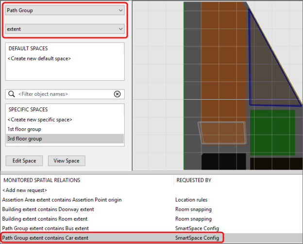
Monitoring the spatial relation in SmartSpace Config SPATIAL PROPERTIES
Run the simulation
Assuming your cell is called “Location Cell 00001”, run the following on a Windows command line:
type path_simulation.xml | ubisense_path_simulation_admin.exe start “Location Cell 00001”
Or this on a Unix-style command line:
ubisense_path_simulation_admin start “Location Cell 00001” < path_simulation.xml
Back in SmartSpace Config, turn on Show foreground objects in the PATHS map. Double-click an object to see its tag being simulated:
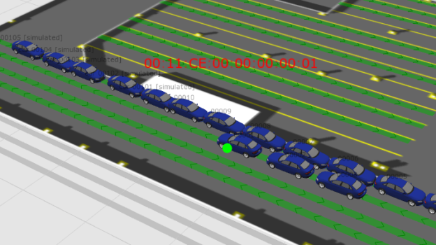
Simulated cars shown on the map in SmartSpace Config PATHS