Example of ACS using the ACS Protocol for spatial relations and message forwarding
Demonstration of ACS with a Workspace and handling spatial relation for devices and workspaces with the ACS Protocol, and demonstration of Message Forwarding with the ACS Protocol.
Preparation of the Ubisense Platform
Creating an area by setting up a file with wall definitions and loading it into ACS.
Configuration of ACS including: Workspaces, External Systems and Device Types.
Show simulations of the ACS Protocol
Preparation of your Environment
Follow the installations instructions for the combination of SmartSpace and ACS and other Ubisense products you require as described in your installation guide.
Use SmartSpace Config to Set up a Site and Add Representations for your Demonstration
Follow the instructions for configuring ACS given in Configuration in SmartSpace.
In particular, you must do the following.
Site Setup
- Add a Geometry Cell to your site.
- Add a Location Cell to your Geometry Cell.
- Extend your Location Cell. In the Cells task, double-click the location cell and, in the Edit the extent of Location Cell dialog, change the Top to 10.
-
Extend your Geometry Cell and Site Cell to contain your Location Cell.
Configuration in ACS
Add a Workspace in ACS
See Workspaces in the ACS Online Help.
- Choose your area.
- Set a suitable name (e.g. "Battery assembly").
- For Height of floor [m] set "0".
- For Height of ceiling [m] set "2".
- Set a suitable geometry for your workspace.
Configure an External System
See External Systems in the ACS Online Help.
- Set a suitable name (e.g. ACSToolController).
- As Type choose Tool Controller.
- Set a suitable description.
- Specify the IP Address of the computer on which the External System will be run.
- Set a suitable Port (e.g. 4646).
- As Protocol choose ACS Protocol.
- As Protocol Version choose 1.0.0.
- Select Remote station is Server.
-
Press OK.
- Go to Operation > Connection status and set the desired state of this external system to Connect.
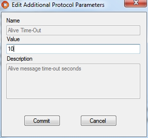
Configure the Additional Parameter for your External System
See Protocols (ACSProtocol) in the ACS Online Help.
- Set parameter Alive Time-Out value to 10.
Add a Device
See Device Types.
- Set a suitable device name (e.g. Battery assembly tool).
- Add a suitable description.
Add a Device Instance
See Device Instances.
- Set a suitable name (e.g. BA Device).
- As Device Type choose Battery assembly tool (the type you created in the previous step).
Enable Static Space Rules for the Device
See Device Instances (Setting Static Space Rules).
- Select your created device (in the upper pane).
-
In the Device Activation pane below, select the ObjectIsLocated Event for your device.
Note: Suffix the name with OILevent to distinguish it from the actual device.
-
Enable the device for the Workspace you created earlier.
- As External System name choose ACSToolController (the external system you last created).
Enable Message Forwarding
See Message Forwarding in the ACS Online Help.
- Select your configured External System for Message Forwarding.
ACS is now configured.
Simulate the ACS Protocol
For your demonstration there is a tool you can use to simulate the ACS Protocol.
Simulate the ACSProtocol
With the tool ubisense_acs_protocol_clientserver.exe you can listen for the ACS Protocol messages. You can find it in the tools directory.
How to use:
ubisense_acs_protocol_clientserver.exe server <IP-Address> <Port> 1
For example:
Demonstration in SmartSpace Config
Using SmartSpace Config, you can show the workspace and the spatial relations.
View the Spatial Relation
By enabling the static space rules in the ACS Main GUI, a monotired spatial relation has been created. Open the SPATIAL PROPERTIES tab and the spatial relation is listed in the lower part of the screen. The requested by column tells you that this spatial relation was requested by ACS.

Add a Representations for the ACS Device
See Adding a representation to an object.
- In the MODEL ASSIGNMENT tab, double-click<Add new object rep> in the lower part of the screen.
- Select the ACS Device type and then the object (e.g. BA device).
- Select a representation for the device and save the assignment.
Note: The device has a default space consisting of a cylindrical space of 10 cm in diameter with zero height which you can amend if required.
Add your Configured Tool to the Object Location
- In the OBJECT PLACEMENT tab, choose ACS Device from the dropdown.
- Drag your device into your area.
- Set the Z-Coordinate to 1.5.
- In SHOW SPATIAL RELATIONSHIPS, select the spatial relationship(s) you defined, here ACS Workspace extent contains ACS Device extent.
Now when your device is contained in a product space the containment is indicated by the containing space displaying in blue.

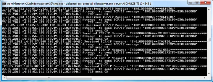
At the command line from ubisense_acs_protocol_clientserver.exe you will see a telegram each time you enter or leave your workspace with your device. You can also see these telegrams in the corresponding Log-File (ubisense_acs_protocol_service*.log).
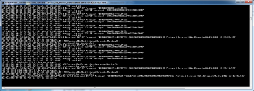
Use the Ubisense Service Manager to Start and Stop the ACSProtocol
At the command line from ubisense_acs_protocol_clientserver.exe you will see a telegram each time the ACSProtocol is stopped. You can also see these telegrams in the corresponding Log-File (ubisense_acs_protocol_service*.log).