Configuring the Cell Hierarchy
Setting up a cell hierarchy involves defining the 3-dimensional space within which the tags will be tracked. A valid cell hierarchy contains three different types of cells that are listed in the following table.
| Cell | Purpose |
|---|---|
|
Site Cell |
The Site Cell represents the entire site that is covered by the D4 RTLS. The Site Cell is created by default when you install the LSC. |
|
Geometry Cell |
The Site Cell contains one or more Geometry Cells. A Geometry Cell represents a smaller area within the Site Cell, such as:
|
|
Location Cell |
A Geometry Cell contains one or more Location Cells. A Location Cell represents a particular region or area where sensors are installed (sensor groups), such as:
In order to allow for continuous tracking of assets, make sure that Location Cells fully cover the areas where tags will be located. |
In a valid cell hierarchy:
- All Geometry Cells are contained by the Site Cell.
-
A Location Cell is contained by a unique Geometry Cell.
- The Location Cells do not overlap.
Tags are tracked as they move into and out of the areas where sensors are installed. Event information is recorded for each Location Cell and passed up the cell hierarchy, from each Location Cell up to the Site Cell.
Creating a Geometry Cell
-
The Site Cell is created by default when you install the Location System Config tool.
-
Ensure that you select a meaningful reference point at your site for the origin of the cell hierarchy.
-
We recommend that you provide a meaningful name for each Geometry Cell.
To create a Geometry Cell:
-
Click the Configure the cell hierarchy tab.
-
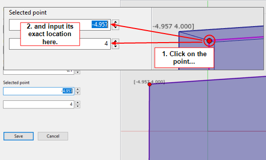
Create a new Geometry Cell by following the onscreen instructions. Using your mouse, add points to create the required extent for the cell – it must cover the area of interest. When you click and drag to add a point, the coordinates of the point are displayed.
Notes:
- When defining the cell extent, you may prefer to work in the 2D view.
-
The Geometry Cell can be any shape. However, we recommend that you create a cell that is reasonably square or rectangular, and that you avoid a long, thin rectangle.
-
If there are multiple Geometry Cells, ensure that they do not overlap.
-
You can display geometry and location cells additional to the cell you are creating by selecting the checkboxes beside their names in the SHOW CELLS list. The additional selected cells are shown as gray rectangles. Use the Show all and Show none buttons to select or unselect all cells.
-
To fine tune the position of a point, click on it and enter the x and y co-ordinates in the editor.
-
Define the top and bottom boundaries of the Geometry Cell to contain the Location Cells (and Sensor Groups).
Field Description Top
The height of the cell in meters. Any heights set for the Location Cells (or the Sensor Groups) contained by this Geometry Cell must be equal to or less than this value.
Bottom
The floor height of the cell in meters. Any floor heights set for Location Cells (or the Sensor Groups) contained by this Geometry Cell must be equal to or greater than this floor height.
Snap Grid
Snaps the cell extent to the nearest intersection of lines in the grid, when you drag the points with your mouse.
-
After you have created the cell, you can use the View options to check it in either 2D or 3D.
- Click Save.
When you create the Geometry Cell, it will not usually be inside the Site Cell. Follow the onscreen instructions in the Errors panel to fix this. The LSC tool automatically fixes the error by enlarging the Site Cell to contain the cell hierarchy.
Creating a Location Cell
-
You can create a Location Cell only if you have set up at least one Geometry Cell.
-
We recommend that you provide a meaningful name for each Location Cell.
To create a Location Cell:
-
Click the Configure the cell hierarchy tab and expand the Geometry Cell that will contain the new Location Cell.
-
Create a new Location Cell by following the onscreen instructions.
Notes:
-
Place the Location Cell extent within a Geometry Cell.
-
The Location Cell can be any shape.
-
If there are multiple Location Cells, ensure that they do not overlap.
-
You can display geometry and location cells additional to the cell you are creating by selecting the checkboxes beside their names in the SHOW CELLS list. The additional selected cells are shown as gray rectangles. Use the Show all and Show none buttons to select or unselect all cells.
-
To fine tune the position of a point, click on it and enter the x and y co-ordinates in the editor.
-
-
Define the top and bottom boundaries of the cell, ensuring that the Location Cell is contained within the Geometry Cell.
-
Save the cell. If there are any errors, the LSC tool displays messages to identify particular problems, and provides options to fix them.
After you have created a cell, you can check it in either 2D or 3D.
Starting Cell Services
Deploy the cell services for the Site Cell, each Geometry Cell, and each Location Cell:
-
Start the Service Manager tool. The Cells option lists all the Site Cells, Geometry Cells, and Location Cells that you have created.
-
You can deploy services for either:
-
The entire Site Cell, including all the Geometry Cells and Location Cells that it contains
-
A particular Geometry Cell or Location Cell
After you deploy services for a cell, the status of the cell changes to Running.
-
At this point, you can assign logging servers as described in Configuring Logging.
Modifying a Geometry or Location Cell
To modify an existing Geometry or Location Cell:
-
On the Configure the cell hierarchy tab, double-click the cell to display the editor.
-
Modify the shape and/or extent of the cell, as required.
-
You can display geometry and location cells additional to the cell you are editing by selecting the checkboxes beside their names in the SHOW CELLS list. The additional selected cells are shown as gray rectangles. Use the Show all and Show none buttons to select or unselect all cells.
-
To fine tune the position of a point, click on it and enter the x and y co-ordinates in the editor.
-
- Click Save.
Deleting a Geometry or Location Cell
To delete a cell:
- On the Configure the cell hierarchy tab, select the cell.
- Press the Delete key.
-
Geometry Cell: The Geometry Cell and its Location Cells are deleted.
-
Location Cell: The Location Cell is deleted.
-
Sensors, Sensor Groups and background objects are not deleted.
-
Using the Service Manager tool, undeploy services for the deleted cells:
- From the Start menu, run Service Manager 3.
- In the SERVICES pane, select All (the top-level folder).
- Click the CELL column heading in the list of services on the right-hand side of the screen to sort the services by cell. Scroll down to display any services associated with an Unknown Cell.
- Select all the services associated with the Unknown Cell and click the Undeploy button.
Guidelines for Assembly Plants
When setting up a cell hierarchy for an assembly plant, ensure that you consider load balancing requirements. A few guidelines are as follows:
-
Split a plant into Geometry Cells.
-
If a production line is made up of parallel bands, ensure that a single band is covered by its own Location Cell.
-
If a production line has a very long, continuous section, split the section into multiple Location Cells.