Graphics in SmartSpace
Graphics in SmartSpace
The following sections guide you through working with 2D and 3D graphics for use in SmartSpace:
Converting a 3D model to a 2D SVG
Converting a 3D model to a 2D SVG
This guide takes you through the steps required to convert a 3D drawing into a 2D graphic in SVG format suitable for import into SmartSpace. Two tools are used in the process: SketchUp® to correctly orient the 3D drawing and export it in a 2D format; Adobe® Illustrator® to edit the 2D image and export it in SVG format.
The guide will cover the following steps:
- Correctly orienting a model for export in SketchUp
- Exporting a 2D model from SketchUp
- Editing a PDF file in Illustrator
- Exporting an SVG file from Illustrator
- Importing the image for use as a representation in SmartSpace
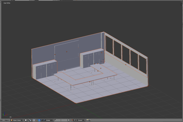
The example shows the conversion of a 3D drawing of a shop floor into a 2D SVG. The source file for the example is provided in a zip file
Software required
The following lists the software required if you want to work through the example.
SketchUp® Pro
The example in this guide uses SketchUp Pro desktop software available from https://www.sketchup.com/.
Note: You cannot use the free web-based version of SketchUp to create a 2D graphic in SVG format from a 3D SketchUp drawing.
Adobe® Illustrator® (trial version)
If you do not have a copy of Adobe® Illustrator®, you can download a free seven-day trial of the software.
Go to https://www.adobe.com/uk/products/illustrator/free-trial-download.html#x and follow the instructions on the Adobe website.
Note: You will be required to supply payment details during the download process.
Correctly orienting a model for export using SketchUp®
- Open SketchUp by typing sketchup in the Start menu.The SketchUp startup window is displayed.
-
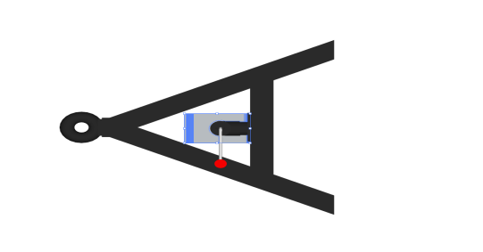
Open the 3D drawing file by choosing File > Open (CTRL+O), going to the directory where you unzipped the example files, and choosing Gearoid Shop Floor 3D - With coloured sections.skp:
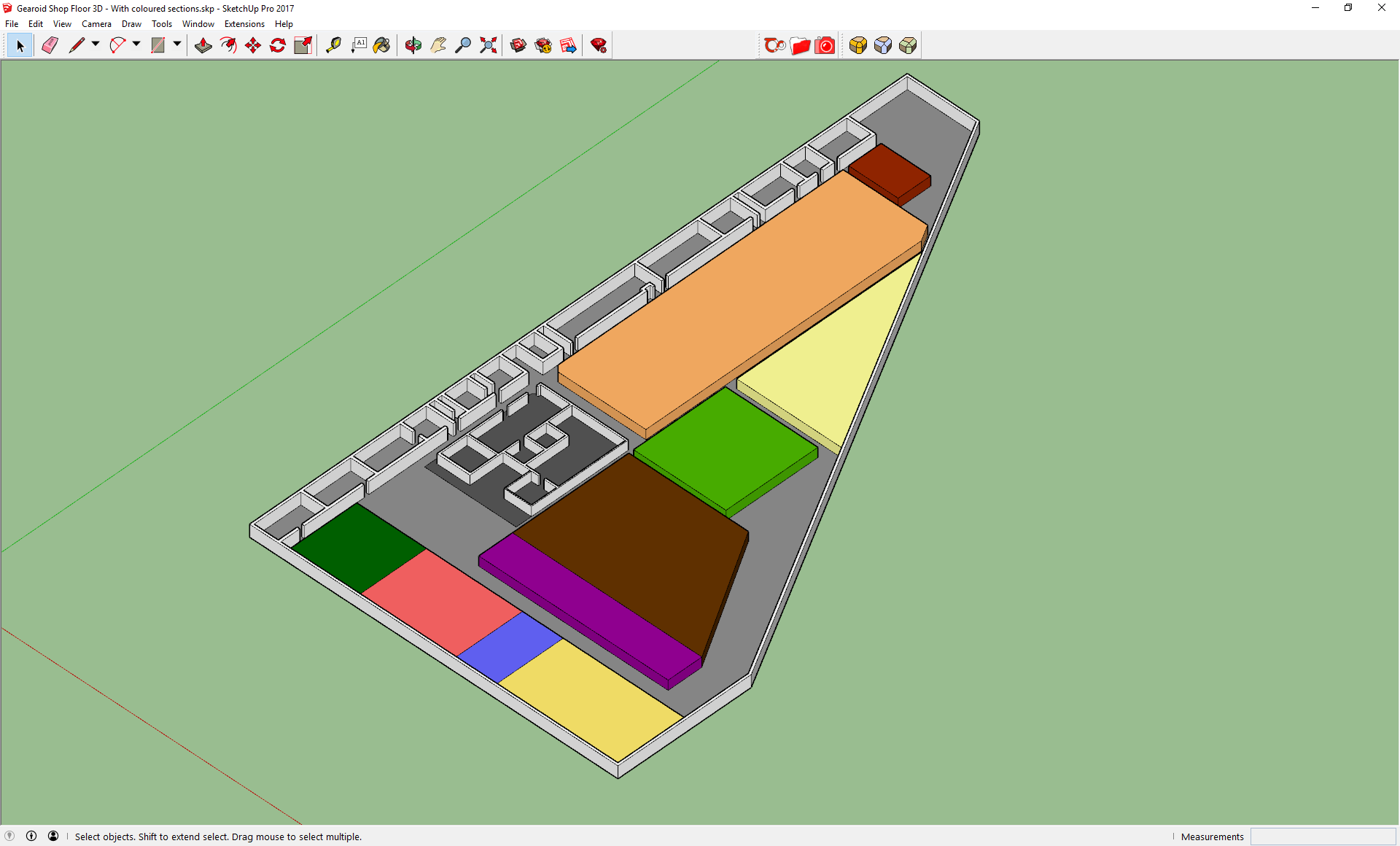
-
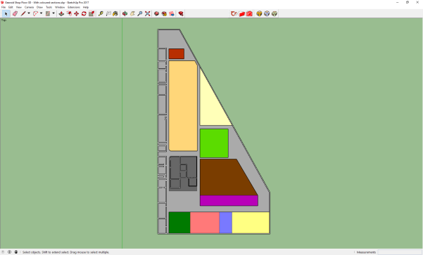
Change the view to top-down by choosing Camera > Standard Views > Top:

-
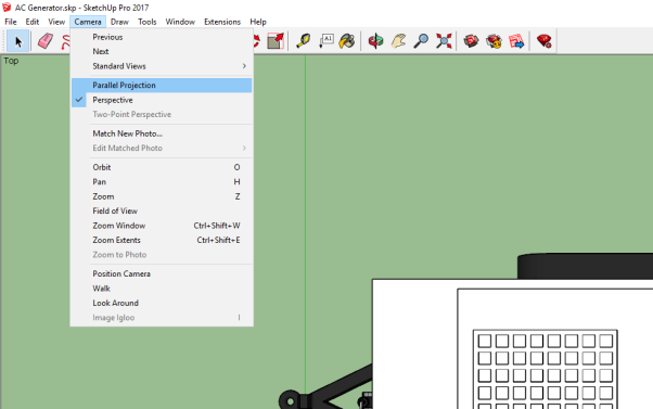
Ensure you are in the Parallel Projection viewing mode by choosing Camera > Parallel Projection.
This will allow you to export a cleaner view of the model:
-
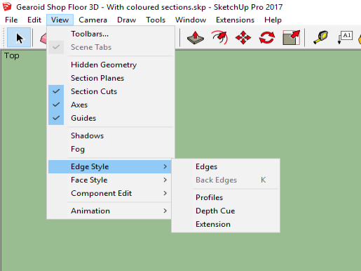
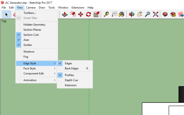
Remove the outlines of the model: these will make the SVG unnecessarily complex.
Deselect Edges and Profiles by choosing View > Edge Style > Edges and View > Edge Style > Profiles respectively.
After deselection, the menu looks like this (there should be no ticks by any of the edge styles):
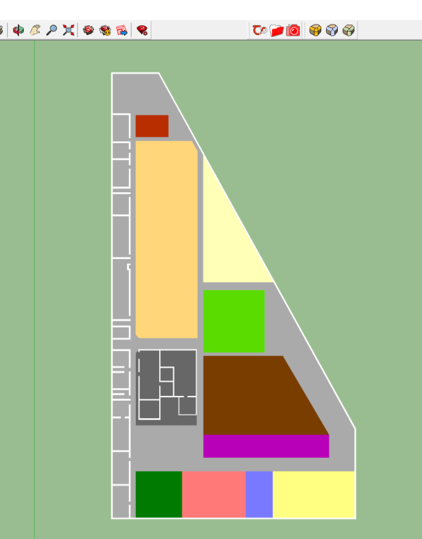
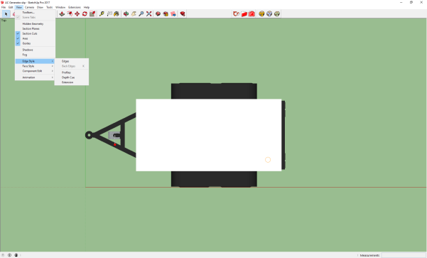
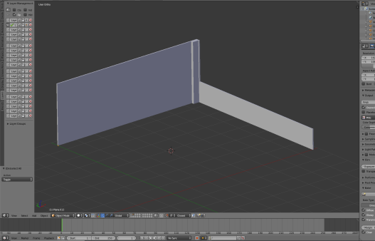
The simplified model looks like this:
Exporting a 2D model from SketchUp
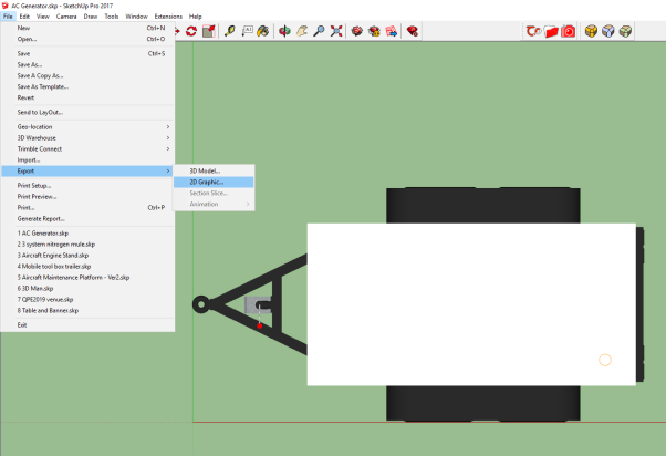
With the model correctly oriented and cleaned up, you can export a 2D file.
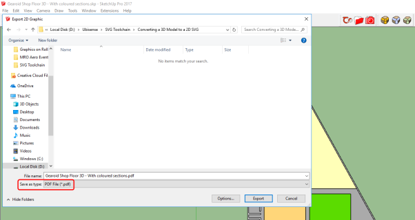
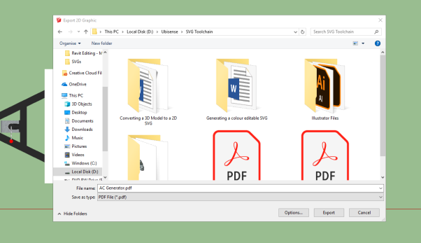
Choose File > Export > 2D Graphic... and save the file, ensuring its file type is PDF:
Editing a PDF file in Adobe® Illustrator®
With the file in 2D format, you can complete the cleanup in Adobe Illustrator.
-
Open Illustrator by typing illustrator in the Start menu.The Illustrator startup window is displayed.
-
Choose File > Open, navigate to the location where you saved the PDF file, and open the file:
-
If necessary, adjust the size of the artboard:
-
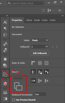
Choose Windows > Artboards. If you are using the Essentials Classic workspace you can choose the Artboards icon from the tools on the right-hand side of the workspace:
- Select Artboard 1 in the Artboards panel and choose Object > Artboards > Fit to Artwork Bounds.
-
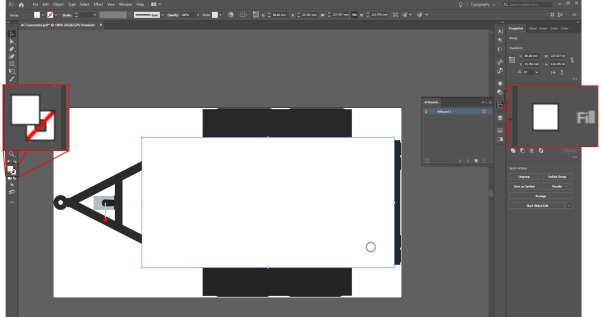
- Set the color of the walls (where you previously removed their outlines in SketchUp).
Hold down Shift and click on each of the walls to select them all:
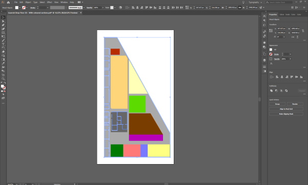
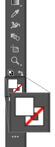
With the walls selected, double-click the Fill icon in the toolbar on the left-hand side of the workspace:
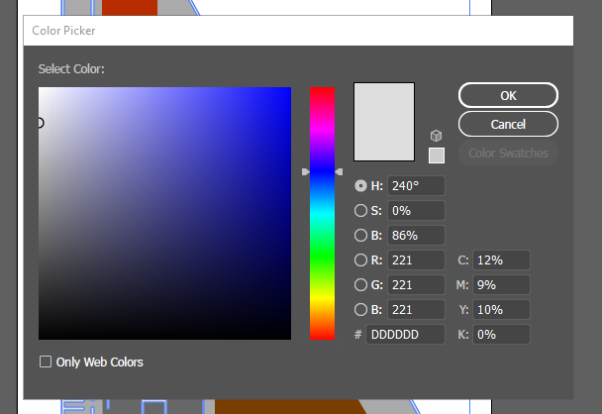
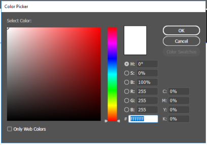
In the Color Picker dialog, drag the circular cursor to select your preferred colour, or type in the colour value (as HSB, RGB, CMYK, Hex#).
For example, enter the RGB values, R: 221 G: 221 B: 221 to choose a light gray:
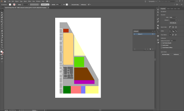
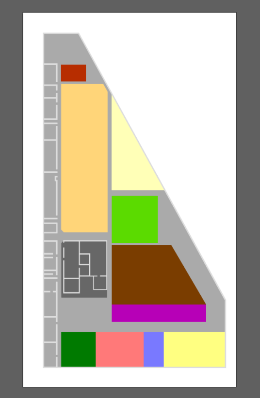
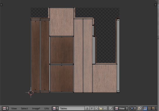
The file looks like this:
-
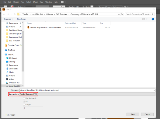
Choose File > Save As... and save the file, ensuring the file type is set to Adobe Illustrator (*.Ai):
Exporting a vector graphic from Illustrator
With file editing complete in Illustrator, the final step is to save the result as a vector file (.SVG).
-
Choose
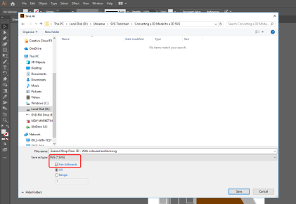

- Give the file a name.
-
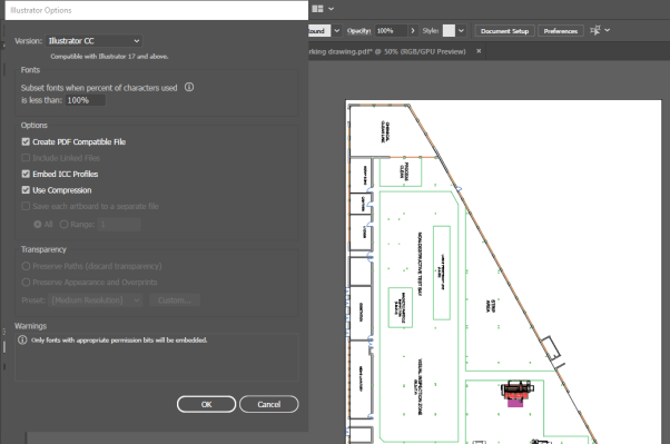
Click Save and then click OK to save the default settings in the SVG Options dialog:
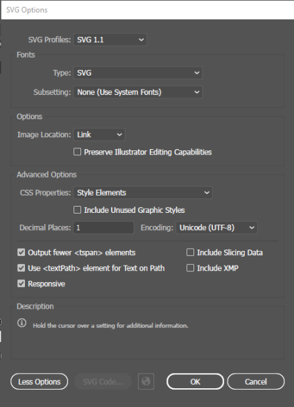
This will provide you with an SVG file which can be successfully imported into SmartSpace.
-
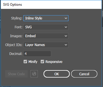
Click Save and the SVG Options dialog displays:
-
Make sure the following details are selected:
-
Styling: Inline style
-
Font: SVG
-
Images: Embed
-
Object IDs: Layer Names
-
Decimal: 4
The Minify and Responsive check boxes should be checked.
-
- With the correct options selected, click OK.
Importing the image into SmartSpace
This section describes how you can import your 2D image into SmartSpace using the SmartSpace Config application. If you need further information on using SmartSpace Config, see
-
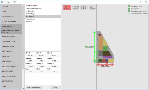
Run SmartSpace Config and open the MODEL IMPORT tab:
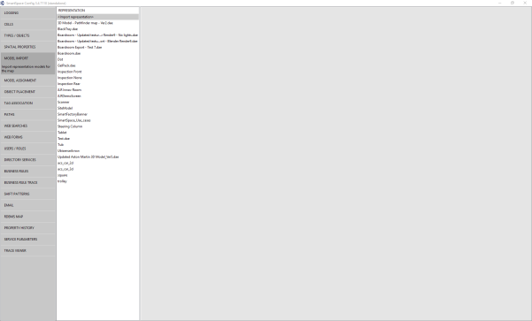
-
Double-click <Import representation>.
-
Navigate to the SVG file which you exported from Illustrator and select it.
The filename, including its suffix, becomes the default name of the representation. Edit the name as required.
-
Click Save.
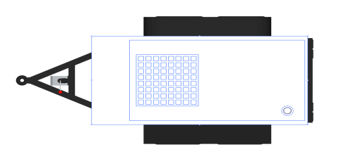
The Model import workspace should look like this:
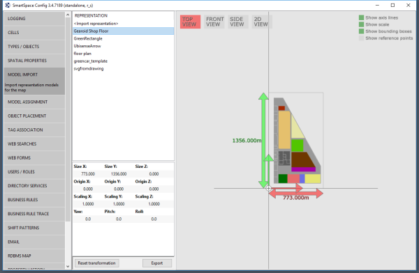
If necessary, you can resize and set the origin of the model. See for further information on importing representations into SmartSpace.
-
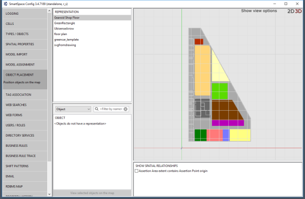
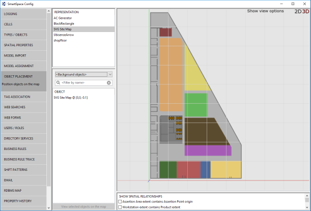
Open the OBJECT PLACEMENT tab.
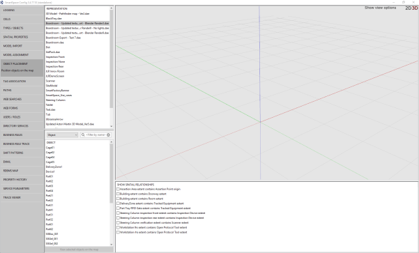
-
Drag the file that you just imported into the workspace:
Constructing a high quality SVG file from a drawing
Constructing a high quality SVG file from a drawing
This guide takes you through the steps required to create a vector graphic from a drawing of a site plan suitable for use as a background representation in SmartSpace.

The vector-editing tool used in the examples is Adobe® Illustrator®. This guide is not intended to provide a complete introduction to Illustrator.
The guide will cover the following steps:
- Setting up a new document (Artboard) in Illustrator
- Importing a working drawing into a new document
- Coloring the constructed vector graphics
- Saving the completed image in SVG format
- Importing the image for use as a representation in SmartSpace
The source file for the example is provided in a zip file SVGToolchain.zip. If you want to work through the instructions step by step, download and unzip the file to a suitable location.
Software required
The following lists the software required if you want to work through the example.
Adobe® Illustrator® (trial version)
If you do not have a copy of Adobe® Illustrator®, you can download a free seven-day trial of the software.
Go to https://www.adobe.com/uk/products/illustrator/free-trial-download.html#x and follow the instructions on the Adobe website.
Note: You will be required to supply payment details during the download process.
Setting up a new document in Illustrator
The following takes you through creating a new document in Illustrator and sizing it to fit your drawing.
-
Open Illustrator by typing illustrator in the Start menu.
The Illustrator startup window is displayed.
-
Create a new custom-sized document, by clicking the Custom icon in the Create a new file panel.
(You can also open a new document by choosing File > New... or clicking the Create New... button.)
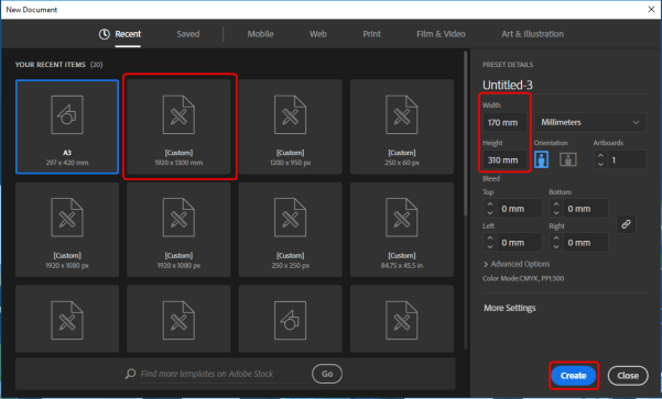
The New Document dialog will appear.
-
Specify the document's size:
- Select a Custom template.
-
Set the dimensions as follows:
Width: 170 mm
Height: 310 mm
- Choose Create.
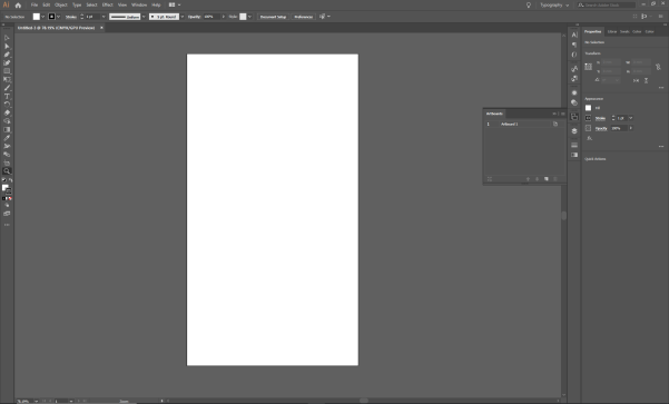
The new blank document looks like this:
Importing a working drawing into the new document
After you have created a blank document, you can import the drawing and copy the required section into the new document. This is described below.
-
Choose File > Open (CTRL+O) and go to the directory where you unzipped the example file.
-
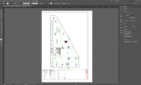
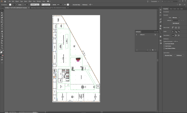
Select SVG conversion working drawing.pdf and click Open to open the PDF file of the SVG conversion working drawing.
The opened PDF looks like this:
-
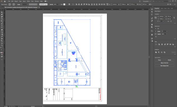
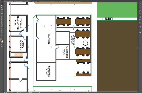
You only require the actual image of the factory (and not the details of the drawing). Select the factory by dragging until you have selected all of it. When you let go of the cursor, the selected objects are highlighted in blue:
- Right click your selection and choose Group.
- Copy your grouped selection, by pressing CTRL+C.
-
Display the new document you created.
All currently open documents will be listed as tabs at the top of the workspace. Click the title of the document you created: it will be called Untitled-x if you haven’t saved it.
-
Paste your selection from the PDF into the new document by pressing CTRL+V.
Move it into position on the artboard by clicking and dragging it.
- Save the new document by choosing File > Save As... and specifying where you would like to save it.
-
Click Save, and, when the Illustrator Options dialog displays, click OK.
Creating a vector graphic based on the working drawing
The next stage in the process involves creating shapes to represent different areas in the building using the drawing as a template.
Drawing shapes to construct the environment – Part 1
The following takes you through constructing the main floor and giving it a color.
-
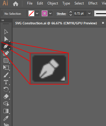
Click the Pen Tool button (or press P):
-
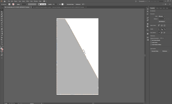
Recreate the shape of main floor by clicking each of the vertices around the factory perimeter in turn and then close the path by clicking on the first anchor point again:
-
Adjust the color in the in the Appearance panel in Properties tab on the right-hand side of the workspace:
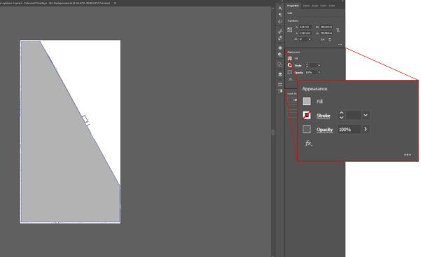
- Set Fill to a shade of gray by clicking the box to the left of Fill and choosing an appropriate color.
- Set Stroke to "no color" by clicking the box to the left of Stroke and choosing [none] (a line through the box indicates this).
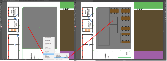
Using layering for efficient construction
While you are constructing multiple shapes based on the working drawing, you don’t want the main floor you have just created to obstruct your view of the drawing. To avoid this you can move it to a separate layer and hide it.
-
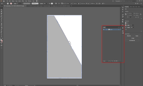
Open the Layers panel.
Click its title in the right-hand part of the workspace, or press F7. You can undock the panel by dragging it into the workspace:
-
Create a new layer by clicking the Page icon:
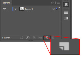
A new layer is added to the list:
-
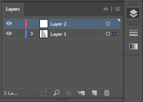
Move the shape you created from Layer 1 to Layer 2:
- In the Layers panel, click the arrow beside Layer 1 to list all the items in that layer.
- Select the shape you drew by clicking the target button.
- Select Layer 2.
- Choose Object > Arrange> Move to Current Layer.
(You can also select the shape you drew and drag it from Layer 1 to Layer 2.)
-
The copied shape will have a red line if it has been successfully placed on the new layer:
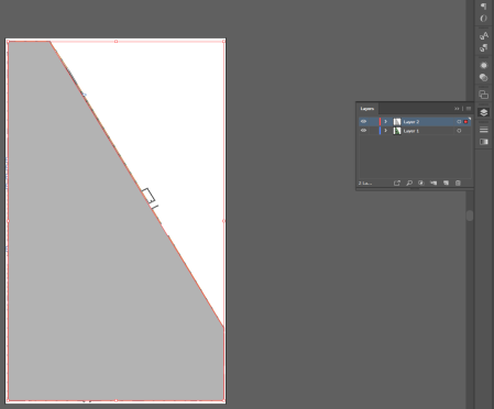
-
After you have moved the shape, lock the layer by clicking in the Edit column (a lock icon appears), and then hide it by clicking the eye icon in the Visibility column (the eye icon disappears):
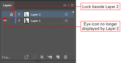
-
You can prevent the working drawing getting in the way by locking its layer. Then create a new layer to place the rest of the shapes on. Your Layers panel will look like this:
Drawing shapes to construct the environment – Part 2
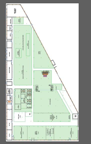
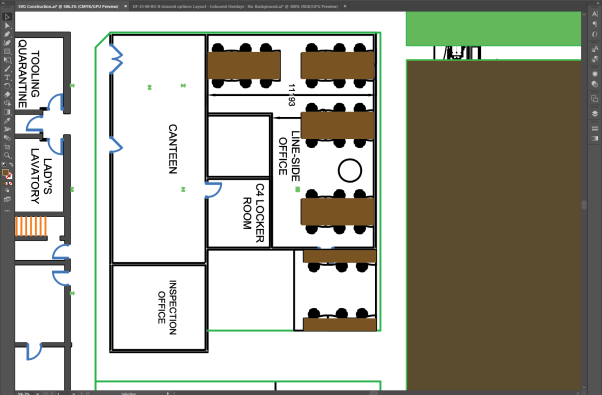
With the main background created and a new layer set up to work in, the next step is to create colored zones/shapes for each of the factory sections: highlighted in green in picture below.
-
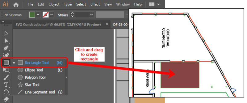
The process for creating each of these areas is exactly the same as creating the main floor. Select the Pen tool and outline each section to create a shape. Alternatively if the shape is a simple rectangle, use the Rectangle tool (located just below the Pen Tool) by clicking and dragging to create a shape of the appropriate size:
-
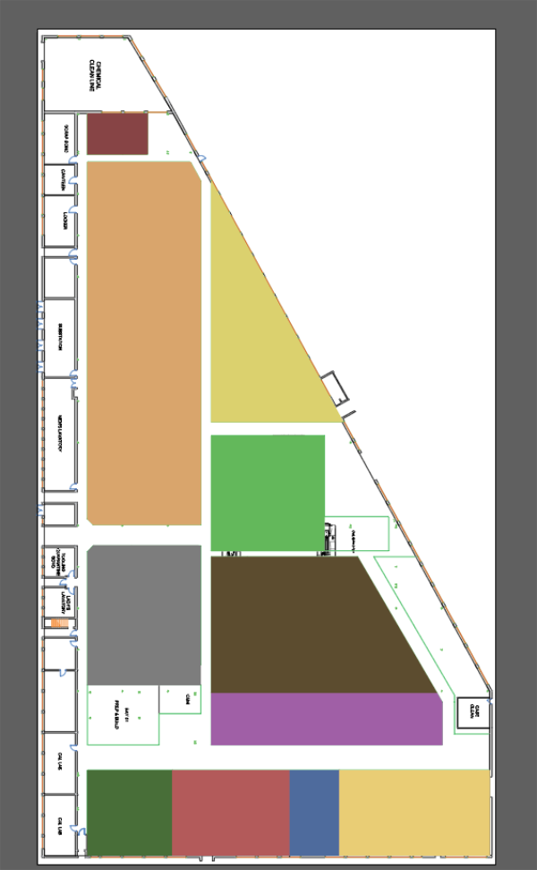
Give each section a different color using the process described above. The file will look something like this:
-
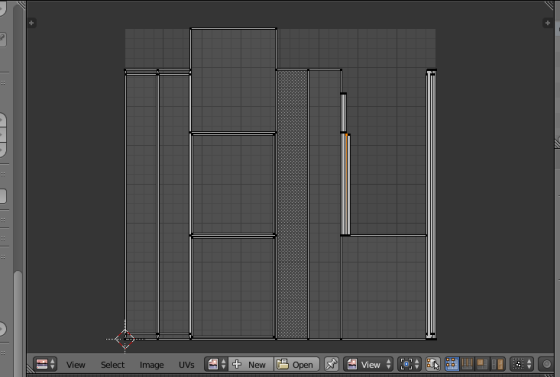
The next step is to construct the walls on the left-hand side of the drawing. This uses a similar process to creating the factory sections, but using only narrow rectangles on top of any walls:
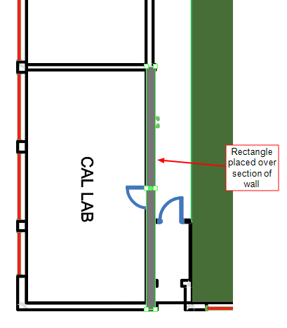
With all the wall sections added, the file looks like this:
Adding final shape details
The following steps take you through adding the final details and the external wall of the building.
-
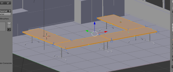
Create the small office with chairs, tables and internal walls.
-
Display details of the office on the drawing by hiding the rectangle that defines it:
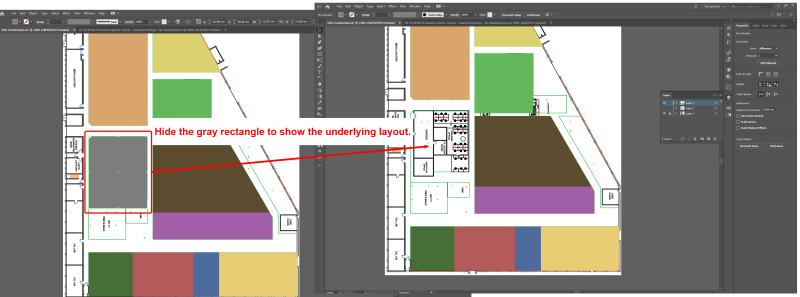
You hide the rectangle by selecting it and choosing Object > Hide > Selection (or by selecting it and pressing CTRL+3).
-
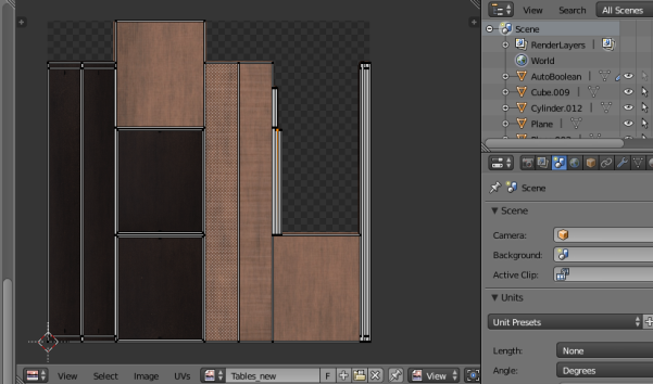
Add the tables, by creating rectangles and coloring them brown:
-
Create the chairs with the Ellipse tool. Clicking and hold the Rectangle tool and choose Ellipse Tool (or press L):
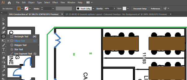
Click and drag diagonally to draw an ellipse. If you want to create circles, hold down Shift and drag to scale the circle.
The area will now look like this:
-
-
Create the internal walls the same way the larger walls were created previously, by generating multiple rectangles anywhere walls are marked out.
The completed result will look like this:
-
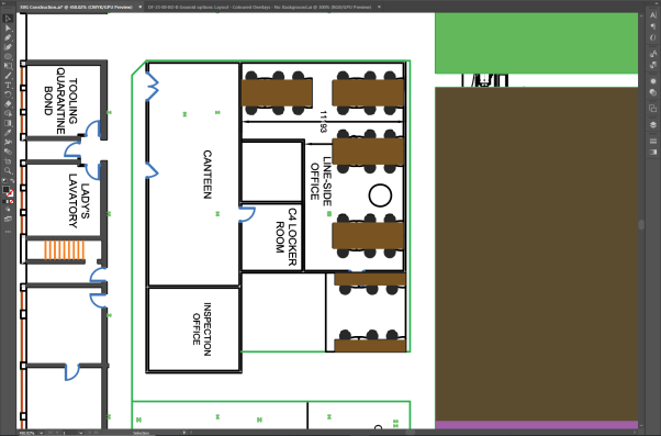
Unhide the floor section by choosing Object > Show All. Make sure it is behind the shapes you have just added, by right-clicking it and choosing Arrange > Send to Back.
-
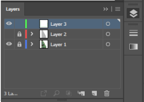
Show the layer with the main background in it again (toggle the Visibility mode beside Layer 2) and hide the working drawing layer (toggle the Visibility mode beside Layer 1).
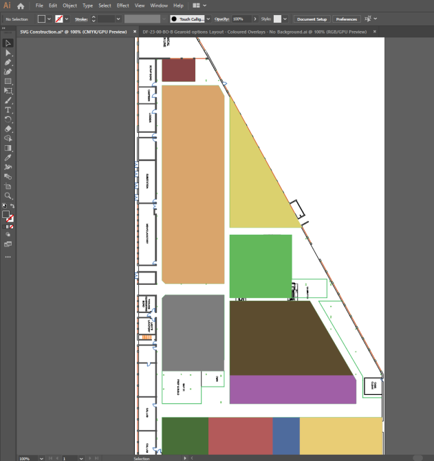
The design now looks like this:
-
Add an outline to the main floor to create the main walls.
-
Copy and paste the main floor. (You will need to unlock the layer first!)
Press CTRL+C, then CRTL+B to paste the new shape directly behind the original one.
-
Hide the original floor shape so you can work exclusively on the copied version.
Select the shape and choose Object > Hide > Selection.
-
With the new floor layer selected, choose Object > Path > Offset Path to display the following dialog:
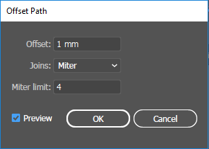
-
At Offset box, type 1 mm.
Make sure you click the preview box so you can see how it will look.
An outline forms as the preview displays:
-
Click OK and a new shape will be generated which is 1 mm larger (offset) all round than the original shape.
Shown here with both layers selected:
-
Select the inner (smaller) shape and choose Object > Path > Divide Objects Below.
It will initially look like nothing has happened. However when you delete the inner shape, only the outer shape will be left.
- Delete the inner shape.
-
Set the color of the outer shape to be a dark gray:
-
-
Unhide the original shape and the completed graphic looks like this:

Exporting a vector graphic from Illustrator
With file editing complete in Illustrator, the final step is to save the result as a vector file (.SVG).
-
Choose
- Give the file a name.
-
Click Save and then click OK to save the default settings in the SVG Options dialog:
This will provide you with an SVG file which can be successfully imported into SmartSpace.
-
Click Save and the SVG Options dialog displays:
-
Make sure the following details are selected:
-
Styling: Inline style
-
Font: SVG
-
Images: Embed
-
Object IDs: Layer Names
-
Decimal: 4
The Minify and Responsive check boxes should be checked.
-
- With the correct options selected, click OK.
Importing the image into SmartSpace
This section describes how you can import your image into SmartSpace using the SmartSpace Config application. If you need further information on using SmartSpace Config, see
-
Run SmartSpace Config and open the MODEL IMPORT tab:
-
Double-click <Import representation>.
-
Navigate to the SVG file which you exported from Illustrator and select it.
The filename, including its suffix, becomes the default name of the representation. Edit the name as required.
-
Click Save.
The Model import workspace should look like this:
If necessary, you can resize and set the origin of the model. See for further information on importing representations into SmartSpace.
-
Open the OBJECT PLACEMENT tab.
-
Drag the file that you just imported into the workspace:
Generating a color-editable SVG
Generating a color-editable SVG
This guide takes you through converting a 3D model into a 2D graphic and editing its code so that its color can be changed within SmartSpace.
The guide covers the following steps:
- Exporting a file from SketchUp in PDF format
- Editing the PDF file in Illustrator
- Exporting the file from Illustrator in SVG format
- Editing the SVG’s code to make it color adjustable
- Importing the image for use as a representation in SmartSpace
The examples show the conversion of a 3D drawing of an AC generator into a 2D SVG. The source file for the example is provided in a zip file ColorEditableSVG.zip. If you want to work through the instructions step by step, download and unzip the file to a suitable location.
Software Required
The following lists the software required if you want to work through the example.
SketchUp® Pro
The example in this guide uses SketchUp Pro desktop software available from https://www.sketchup.com/.
Note: You cannot use the free web-based version of SketchUp to create a 2D graphic in SVG format from a 3D SketchUp drawing.
Adobe® Illustrator® (trial version)
If you do not have a copy of Adobe® Illustrator®, you can download a free seven-day trial of the software.
Go to https://www.adobe.com/uk/products/illustrator/free-trial-download.html#x and follow the instructions on the Adobe website.
Note: You will be required to supply payment details during the download process.
Notepad++
You will need access to a text editor to edit the SVG. The example in this guide uses Notepad++. You can download the Notepad++ software from https://notepad-plus-plus.org/download/ or use your preferred text editor.
Exporting a file from SketchUp in SVG Format
Opening the file in SketchUp
- Open SketchUp by typing sketchup in the Start menu.The SketchUp startup window is displayed.
-
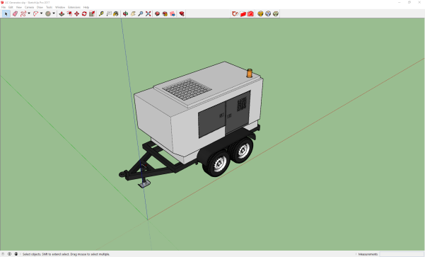
Open a new SketchUp document by choosing File > New (Ctrl+O), going to the directory where you unzipped the example files, and choosing AC Generator.skp:
This will open the document in SketchUp and the window will look like this:
Editing the model for export
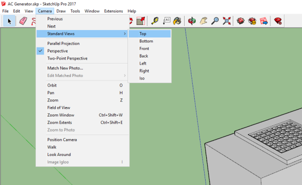
Next change the view in SketchUp so you are looking down on the object. Choose Camera > Standard Views > Top.
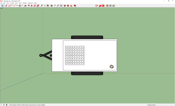
This should now be the view:
Next change the viewing mode from “perspective” to “parallel projection”: Choose Camera > Parallel Projection.
Next remove the outlines of the model by choosing View > Edge Style and deselecting Edges and Profiles.
Once deselected the ticks will disappear beside Edges and Profiles and the object should look like this:
Saving the model as a PDF
With the model lined up, choose File > Export > 2D Graphic.
Next the Export 2D Graphic dialog will appear: make sure the document is saved as the file type “PDF”.
Editing the PDF file in Adobe® Illustrator®
-
Open Illustrator by typing illustrator in the Start menu.The Illustrator startup window is displayed.
-
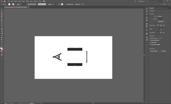
Choose File > Open, navigate to the location where you saved the PDF file, and open the file:
-
To simplify the vector file, select areas of similar color and use the Pathfinder tool to connect the shapes.
Display the Pathfinder tools by choosing Window > Pathfinder or by pressing Shift+Ctrl+F9.
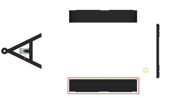
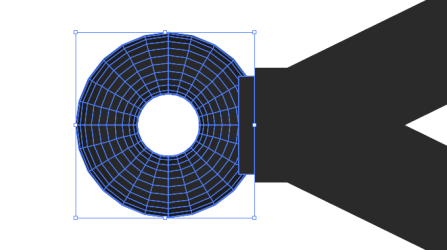
For example, click and drag the cursor over the wheels at the side until all the necessary parts are selected. The selected shapes should look like this:
With the shapes selected, click the Unite (Pathfinder) icon to join the shapes:

The joined shape should now look like this:
-
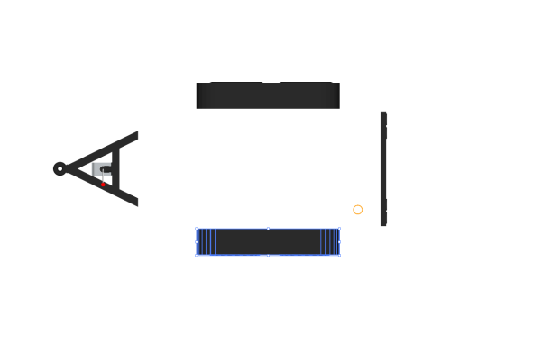
Carry out this same process for any sections composed of multiple shapes of a similar color, some example pictures of sections this can be performed on are as follows:
-
Finish by resizing the artboard so it tightly fits around the object.
-
Choose Windows > Artboards. If you are using the Essentials Classic workspace you can choose the Artboards icon from the tools on the right-hand side of the workspace:
- Select Artboard 1 in the Artboards panel and choose Object > Artboards > Fit to Artwork Bounds.
-
Exporting an SVG file from Illustrator
When the file has been cleaned it can be saved as a vector file (.SVG).
With file editing complete in Illustrator, the final step is to save the result as a vector file (.SVG).
-
Choose
- Give the file a name.
-
Click Save and then click OK to save the default settings in the SVG Options dialog:
This will provide you with an SVG file which can be successfully imported into SmartSpace.
-
Click Save and the SVG Options dialog displays:
-
Make sure the following details are selected:
-
Styling: Inline style
-
Font: SVG
-
Images: Embed
-
Object IDs: Layer Names
-
Decimal: 4
The Minify and Responsive check boxes should be checked.
-
- With the correct options selected, click OK.
Adjusting the SVG’s Code
Now that the SVG has been saved, the next step is to make it color editable. We only want to make the main body editable and to do this we need to find out its color value.
-
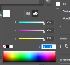
Select the main body color in illustrator, then select the color selection tool on either the left or right side of the workspace:
-
If you select the left option, the following dialog will appear:
-
If you select the right option, the following window will appear (make sure the paint palette icon is selected):
-
-
In either dialog, the color hex code can be found at the bottom. In this instance the code is: #FFFFFF
Remember this code as it will be important later.
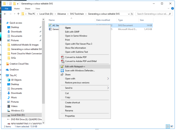
Now use Notepad++ (or your preferred text editor) to edit the code of the SVG.
-
To edit the code of the SVG, in File Explorer right click the filename and choose Edit with notepad++.
-
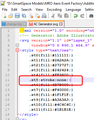
In the Notepad++ window you will see a list of all the color values (Fill Colors):
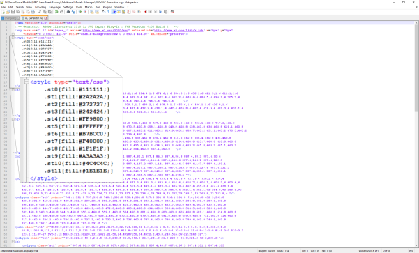
The color you need to adjust is the one whose value was identified previously: #FFFFFF.
-
Make the color adjustable by changing (fill:#FFFFFF;) to (stroke:none;).
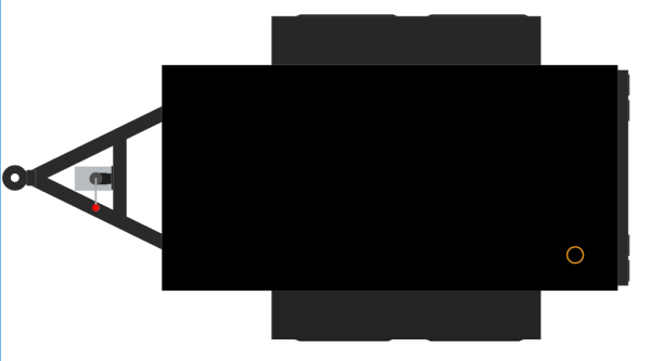
Now if the SVG is opened it should look something like this:
Importing the image into SmartSpace
This section describes how you can import your color-editable 2D image into SmartSpace using the SmartSpace Config application. If you need further information on using SmartSpace Config, see
-
Run SmartSpace Config and open the MODEL IMPORT tab:
-
Double-click <Import representation>.
-
Navigate to the SVG file which you exported from Illustrator and select it.
The filename, including its suffix, becomes the default name of the representation. Edit the name as required.
-
Click Save.
The Model import workspace should look like this:
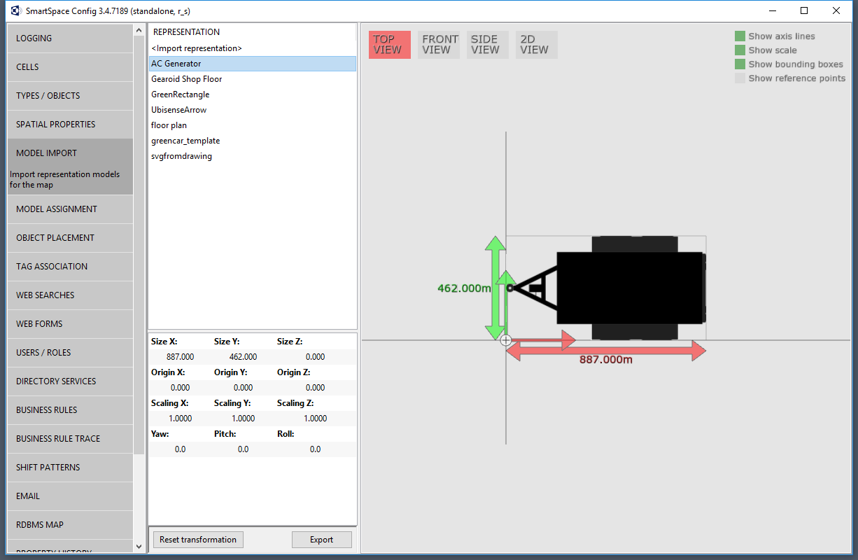
If necessary, you can resize and set the origin of the model. See for further information on importing representations into SmartSpace.
You can now associate the model with a type, and assign instances of the type different colors either manually or using the Business rules engine.
Editing an SVG and converting it to COLLADA
Editing an SVG and converting it to COLLADA
The following document describes the steps needed to construct a suitable SVG to convert into a COLLADA (.DAE) file for import into SmartSpace.
The guide covers the following steps:
-
In Illustrator, how to manually draw shapes around one another
- Tools needed to create shapes in Illustrator
- Using the Shape tool
- In Illustrator how to cut away shapes from one another if they are already overlapping
- Exporting an SVG from Illustrator
- Importing an SVG into Blender
- Exporting a COLLADA file from Blender
- Importing a COLLADA file into SmartSpace
The source file for the example is provided in a zip file SVGtoCOLLADA.zip. If you want to work through the instructions step by step, download and unzip the file to a suitable location.
Software required
The following lists the software required if you want to work through the example.
Blender
You can download the Blender 3D modeling software from https://www.blender.org/ where you can also find comprehensive documentation and tutorials.
Adobe® Illustrator® (trial version)
If you do not have a copy of Adobe® Illustrator®, you can download a free seven-day trial of the software.
Go to https://www.adobe.com/uk/products/illustrator/free-trial-download.html#x and follow the instructions on the Adobe website.
Note: You will be required to supply payment details during the download process.
Why do I need to edit SVGs before I convert them to COLLADA?
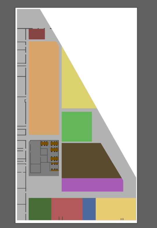
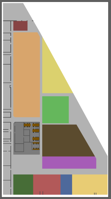
In Constructing a high quality SVG file from a drawing, you are shown how to create SVGs from working drawings and PDF files. Whilst this method is appropriate for 2D SVGs (for example for use in SmartSpace's web map), there can be problems when converting SVGs to COLLADA (.DAE) files. This is because if shapes are drawn on top of other shapes during the creation of the image, there can be problems when the resulting images are viewed in 3D. See the image below where several shapes are competing on the one surface, creating a strange texture:

Such problems can be avoided by altering the method for constructing SVGs in Adobe Illustrator.
The main ways to effectively create or adjust SVGs are:
- Manually drawing shapes around one another to ensure they are not overlapping.
- Cutting away shapes from one another if they are already overlapping.
How to manually draw shapes around one another in Illustrator
This section describes how to create a new SVG from an Illustrator file with no overlapping shapes.
Tools needed to create shapes in Illustrator
Illustrator offers a huge variety of tools for you to explore. However below are some of the main tools used to create and adjust shapes:

Selection tool
The selection tool is used to select, move, rotate and transform previously-constructed shapes.
Direct selection tool
The direct selection tool offers a similar service to the selection tool and also provides editing capabilities at specific points.
Pen tool
Using the pen tool allows you to manually create shapes by clicking anywhere you would like the vertex of a shape to be:

Finish drawing by either clicking on the first point again, or holding down Ctrl and clicking to leave the path open.
Clicking and holding the pen tool can create curves in the shapes.
The pen tool can be used to draw new shapes alongside or around existing shapes to ensure there are no overlaps:

Here the green shape was manually drawn using the pen tool so as to avoid overlapping the blue rectangle.
Using the shape tools
Although the pen tool offers more flexibility, it can often be quicker to draw predefined shapes around other currently existing shapes.
Below is the dropdown menu of the shapes tool (found by clicking and holding the shape tool, on the left-hand side of the Illustrator workspace):

The main tool to be used here (particularly when constructing SVGs of shop floor environments) is the Rectangle Tool.
A good example of where this could be used is for constructing floor markings as well as the floor surrounding them. New shapes can be created by selecting the tool, clicking on the workspace, and dragging. The shapes can then be edited using the selection tool.
Rectangle tool used to make floor markings:

The same tool can then be used to create the floor between them:

The image above includes shapes used for the floor markings and also shapes being used to construct the floor.
This same method can be used throughout the SVG creation, as below where a floor plan is constructed out of multiple shapes. The blue lines are small gaps where the floor markings are placed.

The image below shows a larger section of an example shop floor. For this to be correctly converted to a COLLADA file none of the shapes can be overlapping: they must all be drawn around one another.

Cutting away shapes from one another if they are already overlapping
Where you have an existing image where shapes which overlap, there are tools in Illustrator which allow shapes to be cut away from other shapes to remove the overlap. This can usefully save time by avoiding the need to draw around shapes—both simple and complex ones.
The SVG below was constructed with overlapping shapes:

The instructions below guide you through creating a version of this SVG with no overlapping shapes using the Divide objects below command.
-
Open Illustrator by typing illustrator in the Start menu.The Illustrator startup window is displayed.
-
Choose File > Open,, navigate to the directory where you unzipped the example file, and open the file Dividing objects below SVG.ai.
-
The first step is to select every shape except the main background, make a copy of them, and move them to a new layer. Select all objects except the tables, chairs and walls in the office section. Selected objects are highlighted green:

- With the objects selected, press Ctrl+C, then Ctrl+F to make an exact copy directly in front of the original shapes.
-
With the copied shapes selected, open the Layers panel.
Click its title in the right-hand part of the workspace, or press F7. You can undock the panel by dragging it into the workspace:

-
Create a new layer by clicking the Page icon:
A new layer is added to the list:

If the shapes are still selected there will be a colored square beside the original layer (the color of the square will depend on the color allocated to the layer).
-
To move the shapes to the new layer simply drag the colored square to the new layer. The square will move and the panel will look like this:

- When you have moved the shapes, hide the new layer by clicking the eye icon. (This layer will not as it will be not needed again until the end of the process.)
-
Click the original layer again to return to working on it.
-
Now we want to subtract each shape from the main floor. Illustrator does not allow for multiple shapes to be subtracted at once: each shape must be done one at a time.
We start by working with the green square in the bottom left corner of the SVG:

-
As it is the same height as the shapes to the right of it, the other shapes can be deleted and the green square can be dragged to become the width of all the original squares. This saves time as it means only one shape needs to be subtracted rather than four individual ones.

-
With this shape selected, choose Object > Path > Divide Objects Below.
Note: This command can only be activated if a shape is selected.
The green square will then vanish as it has been used to cut away from the background layer. It will now look like this:

-
Select the rectangle and press Delete. This will leave the shape looking like this:

-
Perform this same process with each main shape one by one until the SVG looks like this:

-
Next, to cut away the walls, rather than selecting each shape one by one, we will use Illustrator's Pathfinder tool which can be used to combine multiple connected shapes to make one.
Every time there is a group of shapes intersecting each other they can be selected and the Pathfinder tool can be used (see below):

With all these shapes selected, locate the Pathfinder tool (you can find it on the right-hand side of the workspace in the Properties panel, or you can open it by choosing Window > Pathfinder or pressing Shift+Ctrl+F9):

-
Choose the Unite icon (the one on the far left). This will convert the multiple selected shapes into one shape.
The newly created shape should look similar to this:

- You can now repeat the process described for the simple shapes above: select the new shape, choose Object > Path > Divide objects below and delete the cutaway shape.
-
Continue using the Pathfinder tool and Divide objects below command wherever you find overlapping shapes until your SVG looks like the image below:

-
The final area which needs to be adjusted is the meeting room with tables and chairs. Start by removing the floor using the same process as before using Divide objects below:

-
Next unhide the copied shapes layer from earlier by going to the layers window and clicking beside the hidden layer so the eye icon reappears.

The SVG should look like the example below:

-
This will most likely cause the chairs, tables and walls to vanish. If this is the case, it can be easily fixed as they are merely hidden behind a shape on the level above. In the Layers panel, select the top layer (Layer 3) and then click and drag it to below the layer with the chairs, etc. on it (Layer 2).
The Layers panel should now look like this:

- Next select the chairs, tables and walls, make a copy of them and paste them onto a separate layer (this is the same process we used in steps 3 to 7). Once again hide this new layer.
-
Next select each table and each chair one by one and use the Divide objects below command to subtract each shape.
After each shape has been subtracted the section should look like this:

-
Finally the walls need to be subtracted. Start by selecting any connecting walls, then use the Pathfinder tool and then Divide objects below for each united shape.
Once all the walls have been subtracted from the background the section should look like this:

-
Unhide the previously hidden details of the chairs, tables and walls and the SVG should look like this:
This is the SVG construction complete.
Exporting an SVG from Illustrator
With file editing complete in Illustrator, the final step is to save the result as a vector file (.SVG).
-
Choose File > Export As... and in the dialog, ensure the file type is set to SVG (*.SVG) and that Use Artboards is checked:
- Give the file a name.
-
Click Save and the SVG Options dialog displays:
-
Make sure the following details are selected:
-
Styling: Inline style
-
Font: SVG
-
Images: Embed
-
Object IDs: Layer Names
-
Decimal: 4
The Minify and Responsive check boxes should be checked.
-
- With the correct options selected, click OK.
Importing an SVG into Blender
If you are new to Blender, the main information you need is:
- how to navigate your way through Blender's user interface
- how to use different editors, such as the Node Editor and UV/Image editor
-
useful keyboard shortcuts (see the Default Keymap section on the Blender website)
Changing the default selection button
By default, Blender uses the right mouse button for selection. You can change this to the left mouse button in the Input tab of the User Preferences dialog: choose Files > User Preferences, open the Input tab, and choose Left at Select With. Click Save User Settings to save this change.
Enabling the Pie Menu add-on
One particularly useful enhancement to the Blender user interface is the Pie menu add-on. This allows you to display via a single key press an array of on-screen options which you can click with your mouse:

To enable this add-on, choose File > User Preferences (Ctrl+Alt+U), select the Add-ons tab, and click the Pie Menu category. Then enable the Pie Menu: UI Pie Menu Official option and click Save User Settings.
Introductory videos
The following videos provide an introduction to the Blender user interface:
-
https://www.youtube.com/watch?v=JYj6e-72RDs&t=830s
This is the first part of a series of videos. If you are interested into developing your Blender skills and gaining a better understanding of the package, you may decide to watch the later parts.
- https://www.youtube.com/watch?v=QAUm_E7ZiQM
To import the SVG into Blender:
- Open Blender by typing blender in the Start menu.The Blender startup window is displayed.
-
Remove all items set up in the standard Blender scene by pressing A to select all items and then X.Click Delete to remove all items.
This leaves the following workspace open in Blender:

-
Choose File > Import > Scalable Vector Graphics (.svg) to open the Import SVG window:

-
Locate where the previously-exported SVG was saved, select the file and choose Import SVG.

-
At first it may appear as though the SVG has not imported. However most likely it is just very small. Therefore zoom in towards the origin using the scroll wheel until the image becomes visible:

-
Increase the size of the model by pressing A to select the entire model. Then press S and drag the mouse pointer to scale the model to a suitable size. Click anywhere on the workspace to set that size:

-
After then model's scale has been set, press A to select the entire model again. Then press Alt+C to open the Convert to dialog:

-
Choose Mesh from Curve/Meta/Surf/Text.
This converts the SVG shapes to a mesh so they can be seen when saved in COLLADA (.DAE) format.
Exporting a COLLADA file from Blender
With the model suitably adjusted, the next step is to export it as a COLLADA (.DAE) file. This will enable model to be dropped into SmartSpace Config.
-
Open the export options menu by choosing File > Export > Collada (Default) (.dae).
-
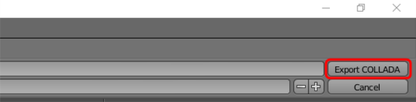
Select the location to save the COLLADA file and then click Export COLLADA:
You will be returned to the main Blender window and a message similar to this will appear in the top banner:

Importing a COLLADA file into SmartSpace
This section describes how you can import the COLLADA file into SmartSpace and add it to your digital environment.
-
Run SmartSpace Config and open the MODEL IMPORT tab:
-
Double-click <Import representation>.
-
Navigate to the COLLADA file which you exported from Blender and select it.
The filename, including its suffix, becomes the default name of the representation. Edit the name as required.
-
Click Save.
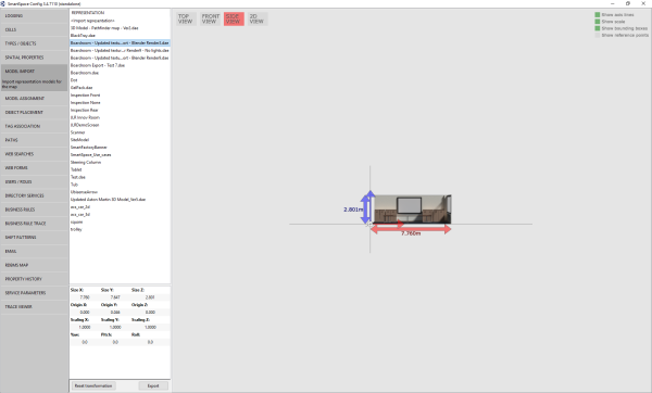
Click TOP VIEW in the Model import workspace for the file to look like this:

If necessary, you can resize and set the origin of the model. See for further information on importing representations into SmartSpace.
-
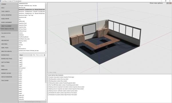
Open the OBJECT PLACEMENT tab.
-
Drag the file that you just imported into the workspace:

Texture baking 3D models
Texture baking 3D models
This guide takes you through the steps required to add textures to 3D models and import these models into SmartSpace. The tool used in the examples is Blender, a free open source 3D creation suite. This guide is not intended to provide a complete introduction to Blender.
The guide will cover the following steps:
- Baking previously-mapped textures to a model
- Exporting baked textures
- Remapping baked textures to a model using a different rendering engine
- Exporting a texture-baked model as a COLLADA file
The examples shown build up the representation of a boardroom. The source files for the examples are provided in a zip file TextureBakingExamples.zip. If you want to work through the instructions step by step, download and unzip the files to a suitable location.
Software required
The following lists the software required if you want to work through the example.
Blender
You can download the Blender 3D modeling software from https://www.blender.org/ where you can also find comprehensive documentation and tutorials.
Starting Blender and exploring its user Interface
Open Blender by typing blender in the Start menu.
The Blender startup window is displayed.
If you are new to Blender, the main information you need is:
- how to navigate your way through Blender's user interface
- how to use different editors, such as the Node Editor and UV/Image editor
-
useful keyboard shortcuts (see the Default Keymap section on the Blender website)
Changing the default selection button
By default, Blender uses the right mouse button for selection. You can change this to the left mouse button in the Input tab of the User Preferences dialog: choose Files > User Preferences, open the Input tab, and choose Left at Select With. Click Save User Settings to save this change.
Enabling the Pie Menu add-on
One particularly useful enhancement to the Blender user interface is the Pie menu add-on. This allows you to display via a single key press an array of on-screen options which you can click with your mouse:
To enable this add-on, choose File > User Preferences (Ctrl+Alt+U), select the Add-ons tab, and click the Pie Menu category. Then enable the Pie Menu: UI Pie Menu Official option and click Save User Settings.
Introductory videos
The following videos provide an introduction to the Blender user interface:
-
https://www.youtube.com/watch?v=JYj6e-72RDs&t=830s
This is the first part of a series of videos. If you are interested into developing your Blender skills and gaining a better understanding of the package, you may decide to watch the later parts.
- https://www.youtube.com/watch?v=QAUm_E7ZiQM
Opening a 3D model in Blender
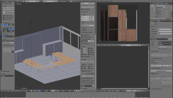
The following steps take you through opening the source files for the boardroom and setting the correct rendering engine.
- Choose File > Open (CTRL+O) and go to the directory where you unzipped the example files.
-
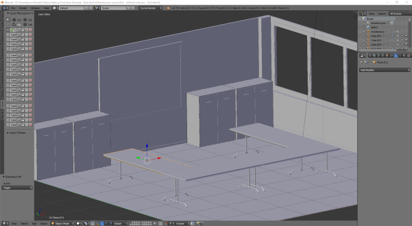
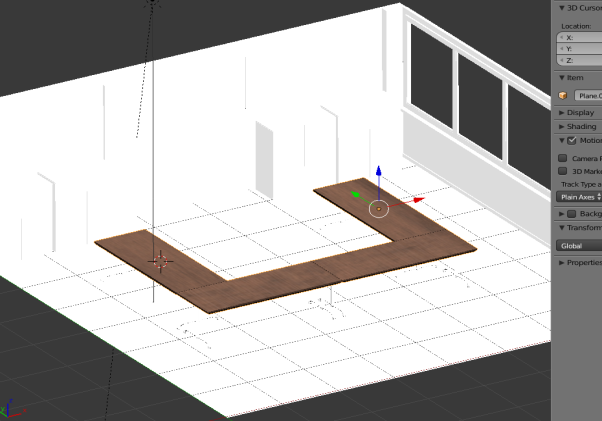
Select Boardroom source files – Without textures.blend and click Open Blender File to display the boardroom with no textures applied:
-
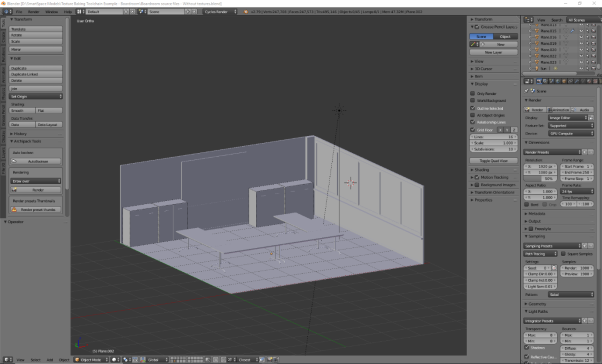
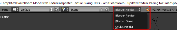
Ensure you are working in the cycles rendering engine.
By default the rendering engine will most likely be set to Blender Render. Change this to Cycles Render by clicking Blender Render in the center of the top menu and choosing Cycles Render from the dropdown.

Adding textures to a 3D object (texture mapping)
The following takes you step by step through UV unwrapping a 3D object and mapping texture maps to it.
If you want to understand more about texture mapping, you might watch the following video: https://www.youtube.com/watch?v=C7jACtwbApI&t=135s
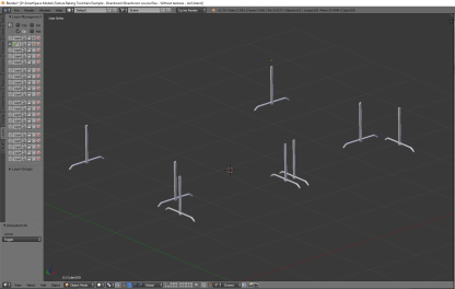
This example will show how to add texture to a specific object (an individual table top). However to save time it is best to join objects with the same texture, unwrap them all, and then map one texture to them all simultaneously. In the example file, the table tops and any other groups of objects that use the same texture have already been joined (by selecting each of the objects and pressing CTRL+J).
To UV unwrap an 3D object and map textures to it:
-
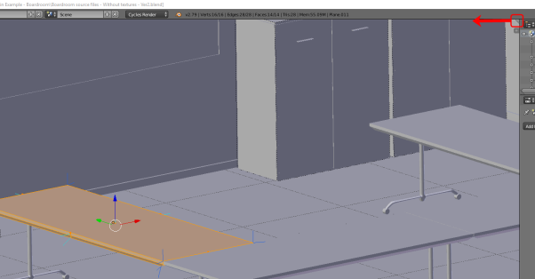
Select the object, here one of the table tops.
It will gain an orange outline when it is selected:
-
Change from Object Mode to Edit Mode by clicking Object Mode in the toolbar and choosing Edit Mode from the menu.
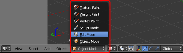
If you have enabled the Pie Menu, you can press TAB and click Edit Mode.
-
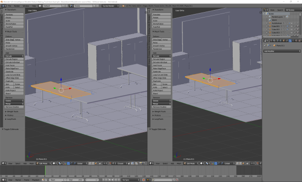
Split the window (called an area in Blender) in two by dragging the area corner inwards.
The screen should now look something like this:
-
Change the Editor Type in the new area to UV/Image Editor by clicking the Editor Type selector—this indicates the current selection is 3D View (the cube icon)—and choosing UV/Image Editor from the menu:
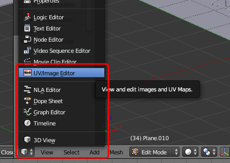
The two areas should now look like this:
-
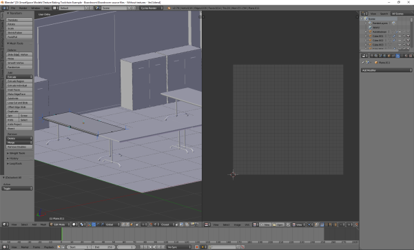
Create an unwrapped version of the 3D model surfaces.
- Make sure you have the 3D View area selected (hover the cursor over it).
- Press A to select everything in Edit Mode.
- Press U to open the UV Mapping menu.
- Choose Smart UV Project and then click OK to accept the defaults in the dialog.

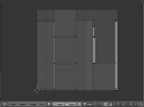
This will create an unwrapped version of the 3D model surfaces:
-
Save the unwrapped surfaces as an image.
Click the New button at the bottom of the area in UV/Image Editor mode, give the image a meaningful name, here Table 1, and choose OK.
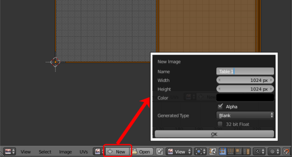
Generally, you should leave the width and height the same. These define the resolution of the image and can be increased if necessary. However be cautious as if the file size of the image textures is too large, they will not successfully import into SmartSpace.
-
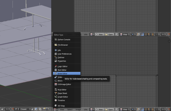
Open a new area and switch to Node Editor.
Create another area and choose Node Editor in the Editor Type selector:
The workspace should now look like this:
-
Create a new material and give it a name.
-
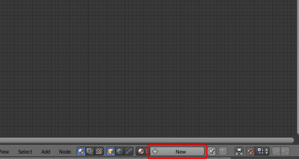
Click New in the toolbar of the area in Node Editor mode.
-
Click the material name (this defaults to Material.xxx) and change it to a suitable name (here TableTop):

-
-
Apply a high quality texture to the object and create a node editing tree.
If you are unfamiliar with Blender, we strongly recommended you watch the recommended videos so as to understand how to create, remove and link nodes in the Node Editor.-
Remove the original Diffuse BSDF node by selecting it and pressing Delete. This leaves just the Material Output node in the editor.
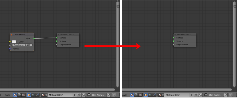
-
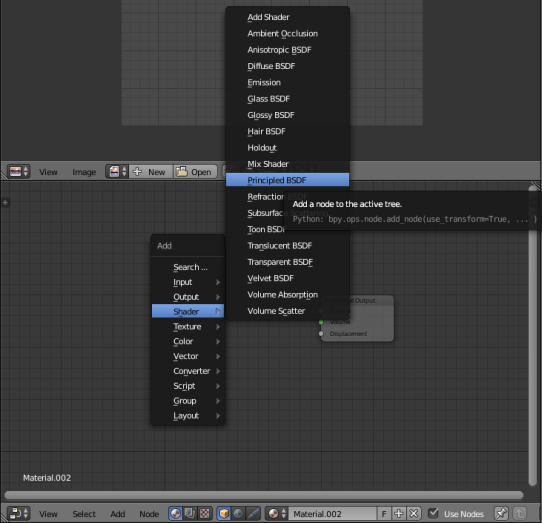
Add a Shader node and link it to the Material Output node.
Press Shift+A to open the Add menu and choose Shader > Principled BSDF:
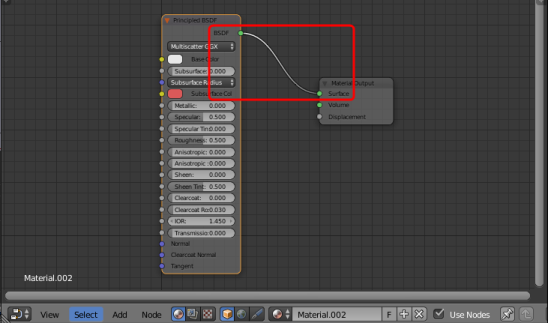
-
Link it to the Material Output node at the Surface point:
-
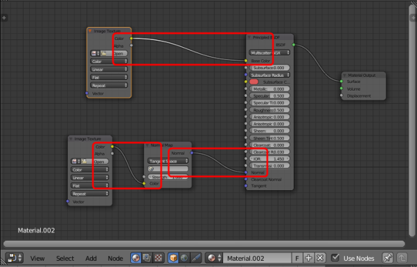
Create further nodes and link them.
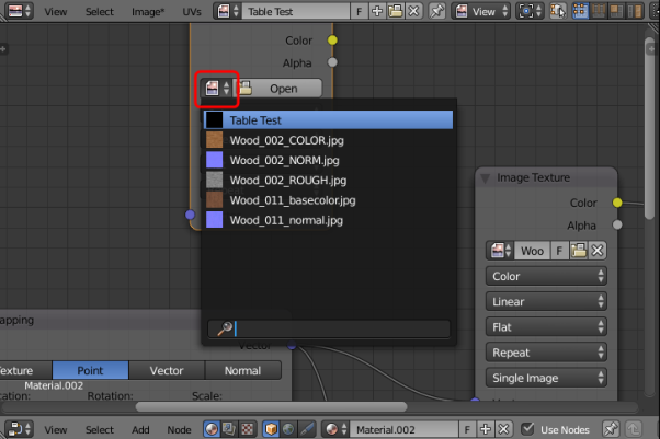
- Create two Image Texture nodes: for each one, press Shift+A to open the Add menu and choose Image > Image Texture.
- Create a Normal Map node: press Shift+A to open the Add menu and choose Vector > Normal Map.
- Link the nodes as shown in the screenshot below:
-
-
Add image files to the Image Texture nodes.
-
On the first image texture node (linked to Base Color) click Open, select the Wood_011_basecolor.jpg file (supplied in ...\Textures to be used in model\Tables) and click Open Image.
-
Add Wood_011_normal.jpg to the other Image Texture node. Set its Color properties to Non-Color Data.

-
-
Add a Texture Coordinate node and a Mapping node.
You may notice when you apply textures that they look too “large". To fix this you need to add a Texture Coordinate node and a Mapping node and link these to the Image Texture nodes.
- Press Shift+A to open the Add menu and choose Input > Texture Coordinate.
- Press Shift+A to open the Add menu and choose Vector > Mapping.
-
Link the nodes as shown in the screenshot below:
-
Adjust the Scale section of the Mapping node, by entering the following values: X: 2, Y: 2, Z: 2.
At the end of these steps, the node editing tree should look something like this:

Baking texture to an object
Now the object has a successfully mapped texture to it, the next step involves “baking” this texture to the object. This essentially involves embedding the texture to the object: this will allow easy navigation around the model without any rendering having to occur (a technique frequently used in video game creation).
The following video explains the concept of texture baking, and the basics of how to successfully do it:
https://www.youtube.com/watch?v=sB09T--_ZvU&t=512s
To bake texture to the table top image:
-
Create a new Image Texture node in the Node Editor:
-
Click the Browse Image to be linked icon to the left of the Open button:
-
Choose the UV Unwrapped file you saved in the previous section.
-
Bake the texture to the image.
-
Select the new Image Texture node (note: this is not linked to any other node).
- Ensure you have Render selected as the type of data to display and edit (The camera button's background should be blue.)
- Click Bake.
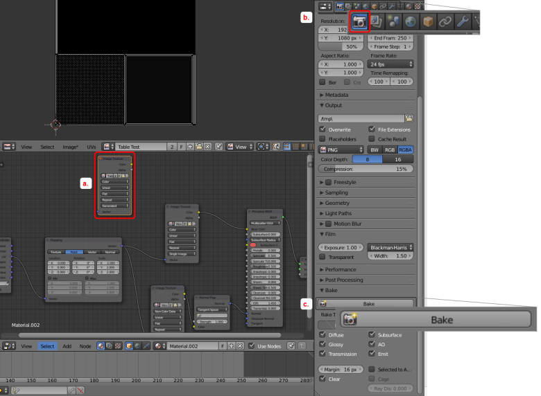
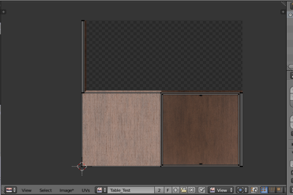
A progress bar at the top of the screen indicates how far the process has progressed. When the texture has baked, the progress bar closes. The UV/Image Editor area should look like this:
-
-
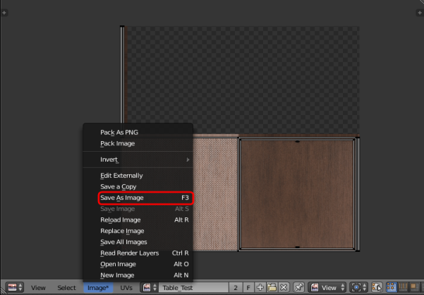
Save the file in a new folder, by clicking Image in the toolbar of the UV/Image Editor area (it will have an asterisk (*) after the option if you have not yet saved) and choosing Save As Image.
The UV unwrap and the texture map you have created (with the pre-joined table top objects) will look like the examples below:

- When the texture has finished baking, in the Node editor create an Emission shader by pressing Shift+A to open the Add menu and choosing Shader > Emission.
-
Link the nodes as shown below:

Note: This disconnects the Principled BSDF shader.
-
Change the display of the 3D View area to Material by pressing Z and choosing Material from the menu.
In the Material area the texture baked file should now be applied to the object.

Completing the boardroom scene
You can continue the process described in the preceding sections for all other objects in the scene to add the remainder of the materials. Suggested materials for each object in the example are given below. You can also find free materials online and use those if you want to make your room unique.
Which materials to use for each object:

- No image textures: create a Principled BSDF shader, change the color to gray and increase the metallic slider value to approximately 0.700.


- No image textures: create a Principled BSDF shader, change the colour to dark gray or black.

- Image Texture 1: Watercolor_Paper_001_COLOR.jpg
- Image texture 2 (Normal map): Watercolor_Paper_001_NORM.jpg

- No image textures: create a Principled BSDF shader, change the color to white or light gray, and increase the metallic slider setting to 0.400.

- No image textures: create a Principled BSDF shader, change the color to gray, and increase the metallic slider setting to 0.200.

Working with a separate rendering engine
The workflow described in the preceding sections used the Cycles Render rendering engine because it is the most interactive method and it creates the best quality textures with relative ease. However, there are issues with exporting the baked textures if you use this engine. For example, if you try to import a COLLADA file of the model you created into SmartSpace, the model will drop in but without any textures. In order to ensure textures stay linked to models when they are imported into SmartSpace, you need to use the Blender Render rendering engine. The steps below take you through remapping the textures you defined in the previous sections to the objects in the model.
To remap textures to objects:
-
Ensure you are working in the Blender Render rendering engine.
Check that Blender Render is listed in the center of the top menu. If not, click on the current rendering engine and choose Blender Render from the dropdown:
-
In 3D View and Object Mode, copy the model by pressing A to select the entire 3D model (all the objects in the model are highlighted in red or orange) and then pressing CTRL+C.
Do not import any lights with the model as these could cause problems in the future. After you have selected all the objects in the model, hold down SHIFT and click any selected light source twice (note: this is two separate clicks and not a double-click).
-
Open a new window in Blender by pressing CTRL+N, delete the default objects, and paste in the copied model by pressing CTRL+V.
A blank solid model should now be sitting in Blender. The next step will be to remap textures to objects. We use the set of four table tops as an example: the same process can be used for all the other objects in the model in turn.
-
Select the table tops, and change from Object Mode to Edit Mode by clicking Object Mode in the toolbar and choosing Edit Mode from the menu.
If you have enabled the Pie Menu, you can press TAB and click Edit Mode.
Table tops in edit mode:
-
Now the object is in edit mode it can once again be UV unwrapped:
- Make sure you have the 3D View area selected (hover the cursor over it).
- Press A to select everything in Edit Mode.
- Press U to open the UV Mapping menu.
- Choose Smart UV Project and then click OK to accept the defaults in the dialog.
Once again this will place a mesh in the UV/image editor area which will look like this:
-
Open the table tops' texture which you saved previously.
Click the Open button at the bottom of the area in UV/Image Editor mode, locate the image file and click Open Image.
When the image file has been selected the UV/Image Editor area should look like this:
-
Create a new material.
-
Create a new area and switch to Node Editor mode. Your workspace should now look like this:
-
In the Node Editor create a new material by clicking the New button:
You don’t need to do anything further in the Node Editor: just leave it blank after creating the new material.
-
-
Create a new texture and apply the texture map you saved previously.
- Ensure you have Texture selected as the type of data to display and edit. (The checkerboard button's background should be blue.)
-
Click New.

- Click Texture.
-
Click the Browse image to be linked icon (beside the New button) and choose the previously saved texture map:

-
To make sure the texture has mapped correctly, in the 3D View area in Object mode, press Z and choose Texture.
The texture area should look something like this if the table tops' textures have been correctly mapped:
-
Carry out this process for all objects in the scene, selecting the correct textures you created previously to match to each one. When they have all been mapped, the model should look something like this:
Exporting the model from Blender
With all the textures successfully remapped, the model can be exported from Blender as a COLLADA (.DAE) file with the textures linked to it.
-
Open the export options menu by choosing File > Export > Collada (Default) (.dae).
-
Select the location to save the COLLADA file and then click Export COLLADA:
You will be returned to the main Blender window and a message similar to this will appear in the top banner:
Importing the model into SmartSpace
This section describes how you can import your 3D model into SmartSpace using the SmartSpace Config application. If you need further information on using SmartSpace Config, see
If you find your import fails, you should check the total file size of the model and its associated files. A collective file size of greater than 50MB is likely to fail.
-
Run SmartSpace Config and open the MODEL IMPORT tab:
-
Double-click <Import representation>.
-
Navigate to the COLLADA file which you exported from Blender and select it.
The filename, including its suffix, becomes the default name of the representation. Edit the name as required.
-
Click Save.
The Model import workspace should look like this:
If necessary, you can resize and set the origin of the model. See for further information on importing representations into SmartSpace.
-
Open the OBJECT PLACEMENT tab.
-
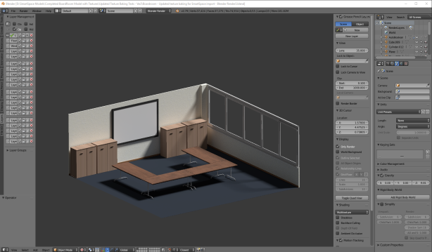
The final textured 3D model when placed in the SmartSpace package should look like this:

Adjusting lighting settings for SmartSpace Config
When a COLLADA file is dropped into SmartSpace Config it may appear quite dark:

The following instructions show you how to use the Registry Editor to adjust parameters in Windows Settings to correct this.
-
Open the Registry Editor by typing regedit in the Start menu.
If you are asked if you want to allow the app to make changes to your computer, choose Yes.

-
To adjust the lighting you must add parameters which can be edited: right click in the Registry Editor window and choose New > String Value.
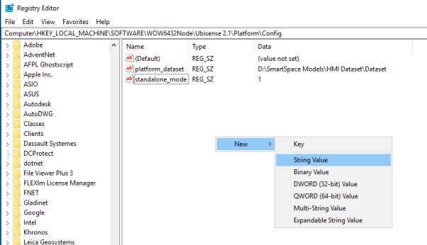
This should produce the following:
-
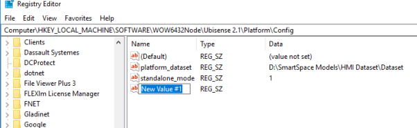
Give the new value the name wx_gl_ambient.
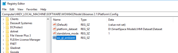
-
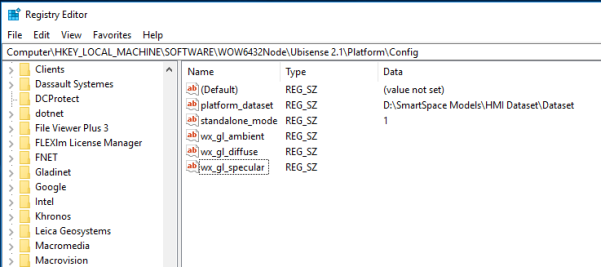
Repeat this process to add two more string values with the names wx_gl_diffuse and wx_gl_specular.
-
Double-click wx_gl_ambient to open the Edit String dialog:

- Type in the value 0.2 and choose OK.
-
In the same way, add the following for the other two values:
- wx_gl_ambient: 0.2
- wx_gl_diffuse: 0.5
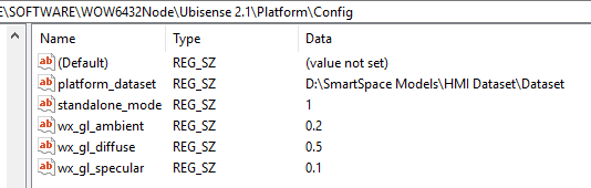
These are the default values for lighting.
-
You can now adjust the default values until the representation displayed in SmartSpace Config looks acceptable. The main lighting value to adjust is wx_gl_diffuse.
Double-click a value and edit the number in the Value data field, then open SmartSpace Config and display the representation. (You will have to restart SmartSpace Config each time you make an adjustment.)
Changing wx_gl_diffuse to 1.5 has proved successful, but each machine may require slightly different values.
With the lighting settings adjusted, the representation should now have improved lighting in SmartSpace Config:


