Examples of Configuring ACS with SmartSpace
The following sections give you examples of configuring ACS with SmartSpace.
Example of ACS with the Atlas Copco OpenProtocol
Demonstration of ACS with an assembly line getting its position information from an external system and handling spatial relation for devices and product spaces with the Atlas Copco OpenProtocol.
Preparing the Ubisense Platform
Creating an area by setting up a file with wall definitions and loading it into ACS.
Configuration of ACS including: Product Types, Product Spaces, Production Lines, Assembly Lines, External Systems and Device Types.
Show Simulations of the ACS Protocol and Atlas Copco OpenProtocol.
Preparation of your Environment
Follow the installations instructions for the combination of SmartSpace and ACS and other Ubisense products you require as described in your installation guide.
Use SmartSpace Config to Set up a Site and Add Representations for your Demonstration
Follow the instructions for configuring ACS given in Configuration in SmartSpace.
In particular, you must do the following.
Site Setup
- Add a Geometry Cell to your site.
- Add a Location Cell to your Geometry Cell.
- Extend your Location Cell. In the Cells task, double-click the location cell and, in the Edit the extent of Location Cell dialog, change the Top to 10.
-
Extend your Geometry Cell and Site Cell to contain your Location Cell.
Create an ACS Area
You can create ACS areas with walls to create a simplified representation of parts of your to aid in configuration. See Creating areas for use in ACS for information on creating areas.
Add Representations
- Import representations and push them to ACS.
- Note: Use two different representations (e.g. BlueCar_template and WhiteCar_template).
Configuration in ACS
Add Product Types in ACS
See Product Types in the ACS Online Help.
- Choose one of your
- Set a suitable Type (Name) and Description.
- Set the timeout to 10 seconds if you get the position from an external system, set no timeout otherwise.
Note: Add two different product types with different representations (e.g. BlueCar and WhiteCar).
Add a Production Line
See Production Lines in the ACS Online Help.
- Set a suitable name (e.g. Main Production Line).
- Set all Product types you want to support in your production line to Supported .
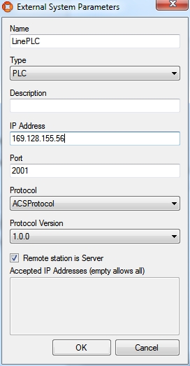
Configure the First External System
See External Systems in the ACS Online Help.
- Set a suitable name (e.g. LinePLC).
- As Type choose PLC.
- Set a suitable description.
- Specify the IP Address of the computer on which the External System will be run.
- Set a suitable Port (e.g. 2001).
- As Protocol choose ACSProtocol.
- As Protocol Version choose 1.0.0.
- Select Remote station is Server.
For example:
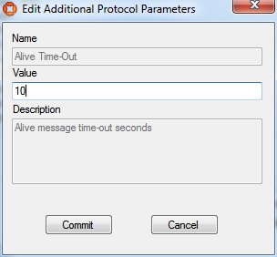
Configure the Additional Parameters for the External System
- For parameter Alive Time-out leave the value at 15
Add an Assembly Line
See Assembly Lines in the ACS Online Help.
- Choose the area you created in SmartSpace Config.
- Set a suitable Name for your assembly line (e.g. Band-01).
- Choose your created Production Line.
- As Location Source choose External System.
- Set the Grid Snapping to 1.00m.
- Set the line geometry for your assembly line.
- On the Externally Driven tab, the parameters for the External System can be configured. (For the Demonstration, select only your configured External System LinePLC and set any Association Id ).
- Set Line Movement to Product offsets.
- Set Clear locations when connection is lost for more than [s] to 10.
- Commit your changes.
Add Product Spaces
See Product Spaces in the ACS Online Help.
- Select your Product Type.
- Add a Product Space.
- Set a suitable name for the space (e.g. Bonnet).
- Set the Grid Snapping to 1.00m.
- Enter a value at Extent ceiling height (e.g. 3m).
- Set a suitable geometry for your Product Space.
For your demonstration, add two different products with different product spaces (Boot for BlueCar and Bonnet for WhiteCar).
Configure the Second External System
See External Systems in the ACS Online Help.
- Add a new external system.
- Set a suitable name (e.g. AC-Controller-Left).
- From Type choose Tool Controller.
- Set a suitable description.
- Specify the IP Address of the computer on which the External System will be run.
- Set a suitable Port (e.g. 4545).
- From Protocol choose Atlas Copco OpenProtocol.
- From Protocol Version choose 1.0.0.
- Select Remote station is Server.
Configure Additional Parameters for the External System
See Protocols (Atlas Copco OpenProtocol) in the ACS Online Help.
For this example it is not necessary to change any additional parameters.
Add a Device
See Device Types in the ACS Online Help.
- Set a suitable device name (e.g. AC-Wireless).
- Add a suitable description.
Add a Device Instance
See Device Instances in the ACS Online Help.
- Set a suitable name (e.g. Device Left).
- As Device Type choose AC-Wireless (the type you created in the previous step).
Enable Product Space Rules for the Device
See Device Instances (Setting Product Space Rules) in the ACS Online Help.
- Select your created device.
- In the Device Activation pane, select the ObjectIsLocated Event for your device.
-
Enable the device for each of the product spaces you created earlier.
-
As External System name select the check box for AC-Controller-Left (the second external system you created).
Enable External System Connectivity
See Connection Status in the ACS Online Help.
Make sure the Desired status column for both the external systems are set as Connected.
ACS is now configured.
Simulating the Two Protocols
For your demonstration there are two tools you can use to simulate the ACS Protocol and the Atlas Copco OpenProtocol
In order to see any output at the cmd you must set an Environment variable, otherwise you can see the output only in the log-File
set UABASEEVENTLOG=1.
Simulate the ACS Protocol
With the tool ubisense_acs_protocol_clientserver.exe you can present the product types moving at your assembly line. Use the Ubisense Application Manager to download the tool (see the Installing Client Machines on Windows section of your installation guide for more information).
ubisense_acs_protocol_clientserver.exe server <IP-Address><Port> 16
For example:
ubisense_acs_protocol_clientserver.exe server 169.128.155.56 2001 16
When the ubisense_acs_protocol_clientserver starts the user has to configure some values:
| Parameter | You enter... |
|---|---|
| Enter line name: | The name of the assembly line, e.g. Band-01 |
| Enter #products: | The amount of products to be generated, e.g. 20 |
| Enter start offset in cm: | The offset from the start of the assembly line, e.g. 0 |
| Enter product distance in cm: | The distance between two products, e.g. 600 |
| Enter Product Type (colon separated): | e.g. BlueCar:WhiteCar |
| Enter first Product ID (numeric): | The ID of the first product to be generated, e.g. 1 |
| Enter speed (m/s): | The speed at which the tags will move along the line, e.g. 0.2 |
| Enter loop pause (s): | The refresh rate, e.g. 1 |
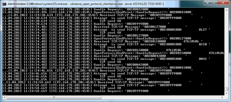
Simulate the Atlas Copco OpenProtocol
With the tool ubisense_open_protocol_clientserver.exe you can present devices using the Atlas Copco OpenProtocol. You can find it in the tools directory.
ubisense_open_protocol_clientserver.exe server <IP-Address><Port> 1
For example:
ubisense_open_protocol_clientserver.exe server 192.168.178.201 4545 1
Demonstration in SmartSpace Config
Now you can show the moving products and the spatial relations in SmartSpace Config.
Add Representations to ACS Product Types
See Adding a representation to a type.
For each of the product types you created in ACS, in the MODEL ASSIGNMENT tab, double-click<Add new type rep> and select the product and the a representation. Save the assignment.
Note: You don't need to use the same 2D representation that you exported to ACS and instead assign a default 3D representation in SmartSpace Config.
Define Spatial Extents for ACS Product Types
See Adding a space property to a type and Configure space properties of types.
For each of the product types you created in ACS:
- In the TYPES / OBJECTS tab, define a space property whose name (e.g. Bonnet) corresponds to the Product Space you defined in ACS.
- In the SPATIAL PROPERTIES tab, define a space that corresponds to the one you defined for the product in ACS.
Add a Representation for the ACS Device
See Adding a representation to an object.
- In the MODEL ASSIGNMENT tab, double-click<Add new object rep> in the lower part of the screen.
- Select the ACS Device type and then the object (e.g. Device Left).
- Select a representation for the device and save the assignment.
Note: The device has a default space consisting of a cylindrical space of 10 cm in diameter with zero height which you can amend if required.
Set the Spatial Relations
See Configure space properties of types.
- In the SPATIAL PROPERTIES tab, double-click<Add new request>.
- In Container, select the product extent you defined.
- In Contained, select extent of 'ACS Device'.
Add your Configured Tool to the Object Location
- In the OBJECT PLACEMENT tab, choose ACS Device from the dropdown.
- Drag your device into your area.
- Set the Z-Coordinate to 1.5.
- In SHOW SPATIAL RELATIONSHIPS, select the spatial relationship(s) you defined.
Now when your device is contained in a product space the containment is indicated by the containing space displaying in blue.

At the command line, from ubisense_open_protocol_clientserver.exe you will see a telegram each time your device enters or leaves your Production Space (if you have set UABASEEVENTLOG=1 as described above).
Example of ACS with tags and a disassociation zone
Demonstration of ACS with an Assembly Line getting its position information from tags using a disassociation zone to send tags to sleep.
Preparation of the Ubisense Platform
Creating an area by setting up a file with wall definitions and loading it into ACS.
Configuration of ACS including: Product Types, Product Type Tag Positions, Production Lines, Assembly Lines, Tag Profiles, Disassociation Zones, Product Tag Association, External Systems and Ident Zones.
Show Simulations of the ACS Protocol.
Preparation of your Environment
Follow the installations instructions for the combination of SmartSpace and ACS and other Ubisense products you require as described in your installation guide.
Use SmartSpace Config to Set up a Site and Add Representations for your Demonstration
Follow the instructions for configuring ACS given in Configuration in SmartSpace.
In particular, you must do the following.
Site Setup
- Add a Geometry Cell to your site.
- Add a Location Cell to your Geometry Cell.
- Extend your Location Cell. In the Cells task, double-click the location cell and, in the Edit the extent of Location Cell dialog, change the Top to 10.
-
Extend your Geometry Cell and Site Cell to contain your Location Cell.
Add Representations
- Import representations and push them to ACS.
- Note: Use two different representations (e.g. BlueCar_template and WhiteCar_template).
Configuration in ACS
Add Product Types in ACS
See Product Types in the ACS Online Help.
- Choose one of your created representations.
- Set a suitable Type (Name) and Description.
- Set NO timeout.
Add two different products with different representations.
Add Product Type Tag Position
See Product Type Tag Positions in the ACS Online Help.
Add the tag position for both product types:
- Select one of your defined product types and add the Tag Position.
- Set a suitable Tag Position Name and Description.
- Set the Tag Position Height (e.g. 0.5m).
- Do NOT check Drive Directly?.
- Set the geometry (point) for the Tag Position.
Check the Tag Position in 2D and 3D mode.
Add a Production Line
See Production Lines in the ACS Online Help.
- Set a suitable name (e.g. MainProductionLine).
- Set all Product types you want to support in your production line to Supported.
Add an Assembly Line
See Assembly Lines in the ACS Online Help.
- Choose the area you created in SmartSpace Config.
- Set a suitable Name for your assembly line (e.g. Band-01).
- Choose your created Production Line.
- As Location Source choose Tag.
- Set the Grid Snapping to 1.00m.
- Set the line geometry for your assembly line.
Activate the tab Tag Settings – see Assembly Lines (Tag Setting tab page - Tag Recognition) in the ACS Online Help.
- For Tag Recognition use the Defaults button to set all values to default.
- For Transport Parameters set the following values:
- Line Width [m]: 2.
- Minimum Carrier Distance [m]: 6.
- Standard line speed [m/s]: 0.2.
- Click "Adapt Length".
- Do NOT add additional Line Sections.
Activate the tab Tag Error Handling (see Assembly Lines (Tag Error Handling) in the ACS Online Help):
- In the Part Error Detection change nothing.
- In the Part Error Recovery change nothing.
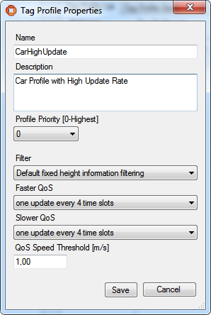
Add Tag Profiles
See Tag Profile Manager (Tag Profile Properties Dialog) in the ACS Online Help.
If you are using a Ubisense D4 system, the Tag Profile Manager dialog has fewer parameters that you can set.
- Set a meaningful name (e.g. CarHighUpdate).
- Add a description.
- Set the Profile Priority to 0.
- Choose a filter (e.g. Default fixed height information filtering).
-
Series 7000 systems only:
- Choose a Faster QoS (e.g. every 4 time slots).
- Choose a Slower QoS (e.g. every 32 time slots).
- Set the QoS Speed Threshold (e.g. 1.00).
For example:
Add at least two different Tag Profiles.
Configure your Tag Profile Sections
See Tag Profile Manager (Tag Profile Sections) in the ACS Online Help.
- Choose your Production Line.
- Choose your Assembly Line Name.
- Add Profile Sections.
- Set your Start Offset.
- Set your End Offset.
- Choose your Profile.
Configure at least two Profile Sections with different profiles.
Configure an Ident Zone for the association
See Ident Zones in the ACS Online Help.
- Set a Name.
- Add a Description.
- Set Height of floor [m] (e.g. 0m).
- Set Height of ceiling [m] (e.g. 3m).
- Choose your Area.
- Set a suitable geometry (trigger zone) for the Ident Zone.
-
Commit your changes.
-
Create an event (Events tab).
-
Give it an appropriate name. (Suffix the name with Event to distinguish it from the actual Ident Zone.)
-
Save changes.
-
Associate the event with Active Type ULocationIntegration::Tag.
Configure an Association Zone
See Association Zones in the ACS Online Help.
- Set a Name.
- Add a Description.
- Choose an Ident Zone.
- Select your first Product Type.
- Choose the Tag Position for this Product Type.
- Select your second Product Type.
- Choose the Tag Position for this Product Type.
- Commit your changes.
For example:

Configure an Ident Zone for the Disassociation
See Ident Zones in the ACS Online Help.
- Set a Name.
- Add a Description.
- Set Height of floor [m] (e.g. 0m).
- Set Height of ceiling [m] (e.g. 3m).
- Choose your Area.
- Set a suitable geometry (trigger zone) for the Ident Zone.
- Create an event (Events tab).
- Give it an appropriate name. (Suffix the name with Event to distinguish it from the actual Ident Zone.)
- Save changes.
- Associate the event with the Product Types as the Active Type.
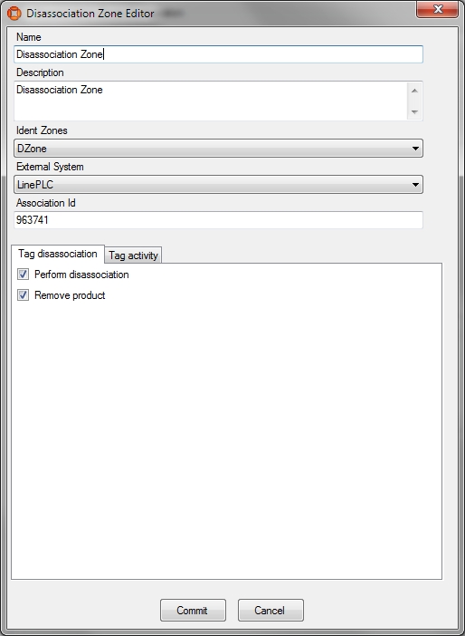
Configure a Disassociating Zone
See Disassociation Zones in the ACS Online Help.
- Set a Name.
- Add a Description.
- Choose your Ident Zone.
- On the Tag disassociation tab, check Perform disassociation and Remove product.
- On the Tag activity tab, check Send tag to sleep and as Wakeup time choose short.
- In the Tag ranges part you can configure whitelists or blacklists for Tag ranges (for the moment leave it blank and check the Not from ranges radio button).
For example:
Configure an External System
See External Systems in the ACS Online Help.
- Set a suitable name.
- As Type choose PLC.
- Set a suitable description.
- Specify the IP Address of the computer on which the External System will be run.
- Set a suitable Port (e.g. 2001).
- As Protocol choose ACSProtocol.
- As Protocol Version choose 1.0.0.
- Select Remote station is Server.
Add your association zone and Disassociation Zone as Associated Objects to your external system (using two different association IDs).
Use the ACSProtocol to Simulate the Association
With the tool ubisense_acs_protocol_clientserver.exe you see the association/disassociation. Use the Ubisense Application Manager to download the tool (see the Installing Client Machines on Windows section of your installation guide for more information).
How to use:
ubisense_acs_protocol_clientserver.exe server <IP-Address><Port> 14
For example:
ubisense_acs_protocol_clientserver.exe server 127.0.0.1 2001 14
You must specify some values from your own example.
Use the tool ubisense_product_tag_simulator to simulate tags moving along your production line. Use the Ubisense Application Manager to download the tool (see the Installing Client Machines on Windows section of your installation guide for more information).
How to use:
ubisense_product_tag_simulator.exe [OPTIONS] <Production Line>
For example:
ubisense_product_tag_simulator.exe -t 100-0-0-1 "MainProductionLine"
See Association of Tags to Products
See Product Tag Association in the ACS Online Help.
- Start the ACS Product Tag Association GUI.
- Set your options (Extras -> Options).
- Set Red Fields for Incomplete Data after [sec] to 5s.
- Set Blinking Fields for Incomplete Data after [sec] to 10s.
- Set the Tag ID prefixes to e.g.. 100- . Ensure that this is consistent with what you have specified with ubisense_product_tag_simulator.
- Choose your association zone.
- Accept your options.

See Association of Products to Tags
If the association isn’t working:
- Check the Assembly Line Messages (Operations -> Live Logs) and if there are no messages then try restarting the ACS Tracking Support service.
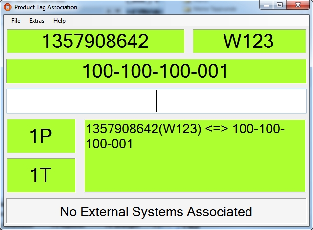
The ACS Product Tag Association tool
Example of ACS using the ACS Protocol for spatial relations and message forwarding
Demonstration of ACS with a Workspace and handling spatial relation for devices and workspaces with the ACS Protocol, and demonstration of Message Forwarding with the ACS Protocol.
Preparation of the Ubisense Platform
Creating an area by setting up a file with wall definitions and loading it into ACS.
Configuration of ACS including: Workspaces, External Systems and Device Types.
Show simulations of the ACS Protocol
Preparation of your Environment
Follow the installations instructions for the combination of SmartSpace and ACS and other Ubisense products you require as described in your installation guide.
Use SmartSpace Config to Set up a Site and Add Representations for your Demonstration
Follow the instructions for configuring ACS given in Configuration in SmartSpace.
In particular, you must do the following.
Site Setup
- Add a Geometry Cell to your site.
- Add a Location Cell to your Geometry Cell.
- Extend your Location Cell. In the Cells task, double-click the location cell and, in the Edit the extent of Location Cell dialog, change the Top to 10.
-
Extend your Geometry Cell and Site Cell to contain your Location Cell.
Configuration in ACS
Add a Workspace in ACS
See Workspaces in the ACS Online Help.
- Choose your area.
- Set a suitable name (e.g. "Battery assembly").
- For Height of floor [m] set "0".
- For Height of ceiling [m] set "2".
- Set a suitable geometry for your workspace.
Configure an External System
See External Systems in the ACS Online Help.
- Set a suitable name (e.g. ACSToolController).
- As Type choose Tool Controller.
- Set a suitable description.
- Specify the IP Address of the computer on which the External System will be run.
- Set a suitable Port (e.g. 4646).
- As Protocol choose ACS Protocol.
- As Protocol Version choose 1.0.0.
- Select Remote station is Server.
-
Press OK.
- Go to Operation > Connection status and set the desired state of this external system to Connect.
Configure the Additional Parameter for your External System
See Protocols (ACSProtocol) in the ACS Online Help.
- Set parameter Alive Time-Out value to 10.
Add a Device
See Device Types.
- Set a suitable device name (e.g. Battery assembly tool).
- Add a suitable description.
Add a Device Instance
See Device Instances.
- Set a suitable name (e.g. BA Device).
- As Device Type choose Battery assembly tool (the type you created in the previous step).
Enable Static Space Rules for the Device
See Device Instances (Setting Static Space Rules).
- Select your created device (in the upper pane).
-
In the Device Activation pane below, select the ObjectIsLocated Event for your device.
Note: Suffix the name with OILevent to distinguish it from the actual device.
-
Enable the device for the Workspace you created earlier.
- As External System name choose ACSToolController (the external system you last created).
Enable Message Forwarding
See Message Forwarding in the ACS Online Help.
- Select your configured External System for Message Forwarding.
ACS is now configured.
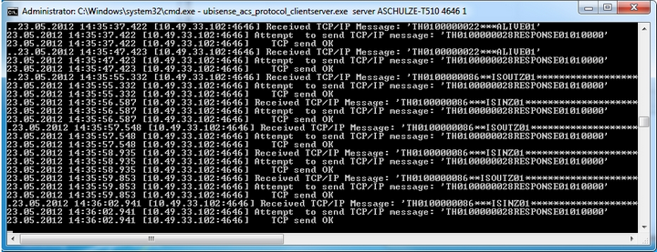
Simulate the ACS Protocol
For your demonstration there is a tool you can use to simulate the ACS Protocol.
Simulate the ACSProtocol
With the tool ubisense_acs_protocol_clientserver.exe you can listen for the ACS Protocol messages. You can find it in the tools directory.
How to use:
ubisense_acs_protocol_clientserver.exe server <IP-Address><Port> 1
For example:
Demonstration in SmartSpace Config
Using SmartSpace Config, you can show the workspace and the spatial relations.
View the Spatial Relation
By enabling the static space rules in the ACS Main GUI, a monotired spatial relation has been created. Open the SPATIAL PROPERTIES tab and the spatial relation is listed in the lower part of the screen. The requested by column tells you that this spatial relation was requested by ACS.

Add a Representations for the ACS Device
See Adding a representation to an object.
- In the MODEL ASSIGNMENT tab, double-click<Add new object rep> in the lower part of the screen.
- Select the ACS Device type and then the object (e.g. BA device).
- Select a representation for the device and save the assignment.
Note: The device has a default space consisting of a cylindrical space of 10 cm in diameter with zero height which you can amend if required.
Add your Configured Tool to the Object Location
- In the OBJECT PLACEMENT tab, choose ACS Device from the dropdown.
- Drag your device into your area.
- Set the Z-Coordinate to 1.5.
- In SHOW SPATIAL RELATIONSHIPS, select the spatial relationship(s) you defined, here ACS Workspace extent contains ACS Device extent.
Now when your device is contained in a product space the containment is indicated by the containing space displaying in blue.

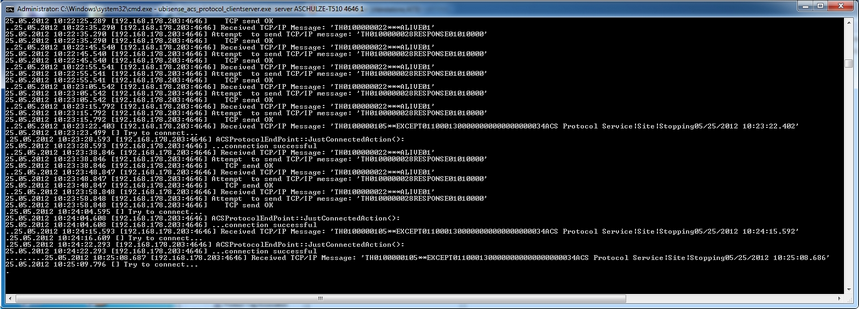
At the command line from ubisense_acs_protocol_clientserver.exe you will see a telegram each time you enter or leave your workspace with your device. You can also see these telegrams in the corresponding Log-File (ubisense_acs_protocol_service*.log).
Use the Ubisense Service Manager to Start and Stop the ACSProtocol
At the command line from ubisense_acs_protocol_clientserver.exe you will see a telegram each time the ACSProtocol is stopped. You can also see these telegrams in the corresponding Log-File (ubisense_acs_protocol_service*.log).