
2.5D Zones and Pitch Compensation
An easy way to describe a zone is to draw it on a map; the zone is assumed to be like a room with vertical walls as defined by the lines on the map. For example, production lines are generally divided into stations, which in 3D space, look like rectangular, vertical-sided boxes arranged along the line, as shown in the following figure.
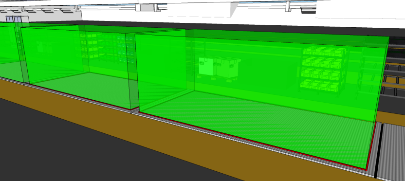
This is a 2.5D zone, which takes up a volume in 3D space, but every horizontal slice through it is exactly the same shape, at any height, so it is completely defined by drawing it out on a map.
A 2.5D zone is easy to understand and communicate. The complicated 3D picture is completely defined by the following 2D map, if you just specify the height of the bottom and top of each zone.
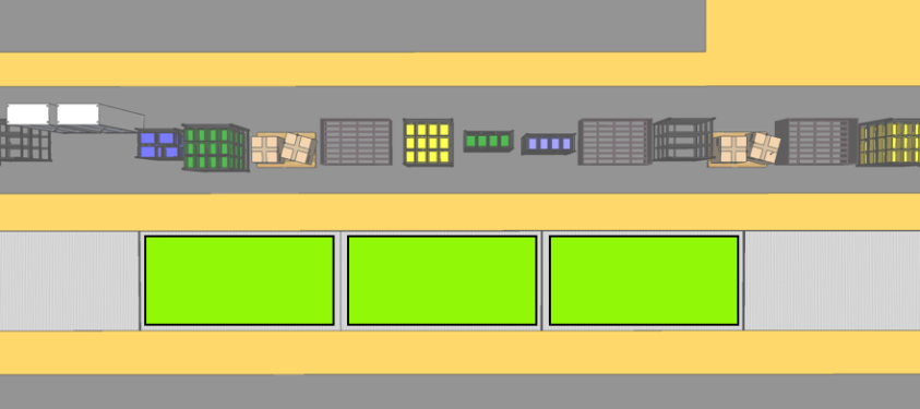
In most cases, the bottom of the zone is on the floor and the top of the zone is less important, so all you require is the map.
We would like to be able to define 2.5D zones in AngleID in a natural way, so that the sides of the space can be defined by setting out a suitable horizontal angle range. However, there is a problem with defining 2.5D zones in AngleID. To obtain good results from the reader, you must usually point it down at the workspace. However, in the figure showing a recipe in 3D space, you can see that the sides of the space marked out by the reader are not vertical. Therefore, you cannot mark out a zone by using an angle range.
The following figure shows the problem.
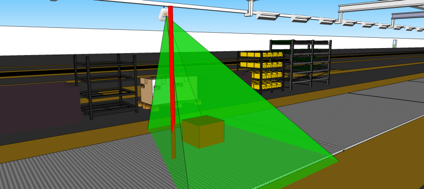
Imagine a tag moving up and down the vertical red rod in the figure. As the tag moves down vertically, it enters the pyramid and the recipe turns on. As it moves up again, it leaves the pyramid and the recipe turns off. This is because the detected azimuth changes as the tag moves up and down; because the reader is no longer pointing out horizontally, the azimuth is no longer a horizontal angle.
To solve this problem, AngleID provides the pitch compensation feature. When you enable pitch compensation for a reader in a recipe, instead of returning the actual azimuth and elevation detected by the reader, it returns the value of the azimuth and elevation that it would have detected if the reader was upright and pointing out horizontally.
The reader calculates the angle at which it is pitched down using a built-in accelerometer (which measures the direction that gravity is pointing relative to the reader), and then applies that rotation to the raw azimuth and elevation that it has detected. This means that, even though the reader points down, the recorded azimuth and elevation readings are exactly the ones you would get if the reader was pointing straight out horizontally.
In this scenario, there is a single reader recipe with a reader pointed down by about 45 degrees, and a tag attached to a tool about two meters away from the reader. The tool can be raised vertically through about 1.5m.
At first, the normal mode is used without pitch compensation, and the range of azimuth and elevation are shown by using the Show Ranges button. As the tag rises and falls, the azimuth changes by a huge amount. Next, the pitch compensation is selected and the process is repeated. When the pitch compensation is selected, the angle readings change to the values that the reader would have obtained if it had been upright. As the tag rises and falls, the azimuth is constant. The azimuth range is visible only due to reader noise.
Therefore, by using pitch compensation, you can point the reader down in the way that provides optimal reader performance, but you can define ranges using the angle readings that you would have obtained if the reader was upright and pointed straight out horizontally.
|
|